Emergency Lighting - Gold Plus Static Inverter Unit
Single Phase 1.5kVA to 40.0kVA
Benefits
n Performance
n Pure sine wave output
n Higher lighting levels when compared
to self contained emergency lighting,
making them ideal for high risk task
emergency lighting requirements
n Most standard AC luminaires can be
used, no need for modification.
It should be ensured that all fittings
selected for emergency lighting
comply with EN60598-2-22, therefore
must not be 2 pin, have glow starters
or be lamps with built in starters
n More energy efficient than self contained
offering cost savings year on year
n Installation
n Removable top entry gland plate
n Integral 100mm plinth to allow good
manouverability
n Smaller cable ratings compared to
traditional AC/DC systems
n Front access enclosure keeping
footprint to a minimum
n Operational
n Central point for maintenance and
testing therefore less disruption to
daily working routines
n Front access cubicles for ease of
maintenance and safe access to
circuit breakers
Key Features
n
n
n
n
n
Pure sine wave inverter
Fully compliant with BS EN 50171:2001
Different outputs available
Battery deep discharge protection
Full LCD and LED display with mimic
diagram for full user information
n Enclosure protection IP21 as standard
(options up to IP54 available)
Applications
n
n
n
n
n
n
n
n
n
Commercial
Retail
Hotels
Sports and Leisure Facilities
Cinemas
Museums
Airports
Hospitals
Manufacturing
The Gold Plus range of Static Inverter Units offer a reliable and proven
solution for Emergency Lighting requirements including an inverter
specifically designed to power lighting loads.
The units are compact, easily maintained and fully compliant to BS EN50171:2001
System Operation
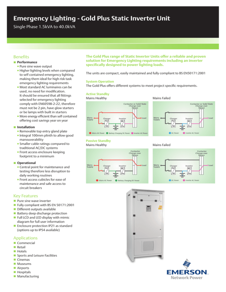
The Gold Plus offers different systems to meet project specific requirements.
Active Standby
Mains Healthy
Mains Failed
Passive Standby
Mains Healthy
Mains Failed
Emergency Lighting - Gold Plus Static Inverter Unit
Single Phase 1.5kVA to 40.0kVA
Technical Data
Enclosure
n 2mm Zintec Steel - RAL 7035
n Key lockable doors
n Front access enclosure
n Top cable entry with removable gland plate
n Access to circuit breakers via front hinged and
lockable cover
n IP21 for standard enclosures
(options up to IP54 available)
Battery Charger
n Microprocessor controlled, power factor corrected
n Temperature compensated
n Constant voltage, current limited rectifier
n Protection against reverse battery polarity
n Protection against battery over voltage, input mains
low and mains surges
n Low volts disconnect
Inverter
n High frequency microprocessor controlled
PWM IGBT inverter
n Pure sine wave output
n Galvanic isolation with ground neutral
Load Circuit
n Single or multiple outputs can be offered as maintained,
non maintained or a combination of both
n Changeover Contacter (passive standby)
n Electronic Switching Device (active standby)
Remote Monitoring
n Volt free contact for: Common Alarm, Mains Fail,
Charge Fail, Overload
n Remote alarm contact rating: 1A, 24V DC
Datalogger
n 200 alarm records and 200 battery records can be
accessed via the display
Manual Battery Test
n A 10 minute test and deep discharge test are
selectable via the display
System Input
Voltage: 230VAC 1ph or 400VAC 3ph
Voltage range: +/- 10%
Frequency: 50Hz +/- 5%
System Output
Voltage: 230VAC 1ph
Voltage regulation: +/- 1%
Output frequency: 50Hz
Frequency regulation: +/- 0.1%
Wave form: Sine wave
DC / AC Efficiency: >90%
Load power factor: 0.7 lag to 0.9 lead
Overload: 120% continuous
Operating temperature: 0 to 40°C (inverter only)
Recommended battery operating temperature range for optimum
life and performance is 20°C +/- 5°C
LCD Digital Meter Readings
n
n
n
n
n
Mains input - voltage and frequency
Inverter - AC voltage / current / kVA / % load / frequency
DC volts
DC discharge current
Charge current
Alarms
n
n
n
n
n
n
n
n
n
n
n
n
Mains fail
Charge fail
Inverter fail
Boost charge (NiCd batteries only)
Battery Disconnected
DC over voltage
Battery test - 10 minute / rated standby test
Auto test
Inverter overload
Short circuit
Over temperature
Battery under voltage
Fully Compliant with the Following Standards
Auto Battery Test
n A weekly or monthly test can be selected via the display
Display
n Consists of 4 x 20 character LCD Dot-Matrix with LED
indication and scrolling command buttons
Emerson Network Power
George Curl Way, Southampton SO18 2RY, UK
Tel: +44 (0)23 8061 0311
Fax: +44 (0)23 8061 0852
UK.Enquiries@Emerson.com
EmersonNetworkPower.eu
n
n
n
n
Emergency lighting EN 50171
Safety EN 62040-1
EMC Emissions EN 61000-6-3
EMC Immunity EN 61000-6-2
Emerson. Consider it Solved., Emerson Network Power and the
Emerson Network Power logo are trademarks and service marks of
Emerson Electric Co. or one of its affiliated companies.
©2014 Emerson Electric Co. All rights reserved.


