CE 428 Water and Wastewater Treatment Design Sludge Processing
advertisement
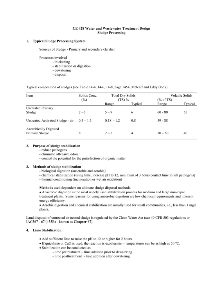
CE 428 Water and Wastewater Treatment Design Sludge Processing 1. Typical Sludge Processing System Sources of Sludge - Primary and secondary clarifier Processes involved - thickening - stabilization or digestion - dewatering - disposal Typical composition of sludges (see Table 14-4, 14-6, 14-8, page 1454, Metcalf and Eddy Book) Item Solids Conc. (%) Total Dry Solids (TS) % Range Typical Volatile Solids (% of TS) Range Typical Untreated Primary Sludge 2-6 5–9 6 60 - 80 Untreated Activated Sludge - air 0.5 – 1.5 0.18 - 1.2 0.8 59 - 88 Anerobically Digested Primary Sludge 8 2–5 4 30 – 60 65 40 2. Purpose of sludge stabilization - reduce pathogens - eliminate offensive odors - control the potential for the putrefaction of organic matter 3. Methods of sludge stabilization - biological digestion (anaerobic and aerobic) - chemical stabilization (using lime, increase pH to 12, minimum of 3 hours contact time to kill pathogens) - thermal conditioning (incineration or wet air oxidation) Methods used dependent on ultimate sludge disposal methods. Anaerobic digestion is the most widely used stabilization process for medium and large municipal treatment plants. Some reasons for using anaerobic digestion are low chemical requirements and inherent energy efficiency. Aerobic digestion and chemical stabilization are usually used for small communities, i.e., less than 1 mgd plants. Land disposal of untreated or treated sludge is regulated by the Clean Water Act (see 40 CFR 503 regulations or IAC567 - 67 (455B) - known as Chapter 67). 4. Lime Stabilization Add sufficient lime to raise the pH to 12 or higher for 2 hours If quicklime or CaO is used, the reaction is exothermic – temperatures can be as high as 50 oC. Stabilization can be conducted as - lime pretreatment – lime addition prior to dewatering - lime posttreatment - lime addition after dewatering Lime Dosage Sludge Solids Concentration (%) Primary Waste Activated Anaerobically Digested Septage 5. Lime Dosage lb Ca(OH)2/ton dry solids Range Average 120 – 340 240 420 – 860 600 280 – 500 380 180 – 1020 400 3- 6 1 – 1.5 6–7 1 – 4.5 Anaerobic Digestion – Principle (see Figure 7 - ) - Hydrolysis – first stage, break down of large complex molecules into smaller molecules that can be transported into cells and metabolized - Acetogenesis and acid formation – fermentative step whereby the smaller molecules are fermented into volatile organic acids (acetic acid, butyric acid, propionic acid), hydrogen and carbon dioxide. Bacteria that produce hydrogen and acetic acid are called acetogens. - Methanogenesis – formation of methane by methanogens, acetic acid to methane, hydrogen plus carbon dioxide to methane. Factors Affecting Anaerobic Process - Oxygen - Absence of free oxygen needed for methanogenesis to grow (strict anaerobes) - Redox potential needed < - 330 mV - Temperature – optimal: mesophilic (15 – 40o C), thermophilic (45 – 60o C). lower temperatures (psychrophilic), rate of digestion decreases - pH – optimal pH range for methanogens: 6.5 to 7.5, typical pH 7. Note that the acetogenesis produces volatile organic acids that will depress the pH which will in turn inhibit methanogens. A synergistic relationship is therefore needed to maintain the pH around neutral. - Hydrogen - Hydrogen plays a role in limiting the conversion of fatty acids and alcohols by acetogenic bacteria. Low hydrogen pressure is maintained by conversion of CO 2 and H2 to CH4 by methanogenic bacteria - Inhibitors - Sensitive to various inhibitors such as common ions, organic compounds Common ions Parameter Sodium Potassium Calcium Magnesium Ammonium (total) Simulating Effect 100 - 200 200 - 400 100 - 200 75 - 150 50 - 200 Moderate Inhibition 3500 - 5500 2500 - 4500 2500 - 4500 1000 - 1500 1500 - 3000 Significant Inhibition 8000 12000 8000 3000 3000 Biogas Production Potential Maximum theoretical yield of methane: ________________ m3 CH4/kg COD (5.6 ft3/lb) The above is based on a stoichiometric utilization of oxygen for the complete conversion of CH 4 to CO2 and H2O In reality, the yield is lower, usually 0.20 m3 CH4/kg COD, however, literature values ranged from 0.1 to 0.35 m3 CH4/kg COD Typical gas composition : 60 – 70% methane, 30- 40% carbon dioxide, with small amounts of hydrogen sulfide, ammonia, water vapor Energy content: 22 – 26 MJ/m3 (591 – 698 BTU/ft3) 6. Types of Anaerobic Digestion Systems include (See Figure 14-20): (i) ____________________ (mesophilic) – functions as digester, sludge thickener and supernatant formation - untreated sludge is introduced into the zone where the sludge is actively digesting and the gas is released - gas rises to the surface, stratification occurs - digested sludge removed from the bottom - not more than 50% of the volume is used for digestion (ii) ____________________ (mesophilic) - sludge is mixed by gas, recirculation, mechanical mixers, pumping or by draft-tube mixers - sludge heated to achieve optimum digestion rates - reduction in total solids 45 to 50% (iii) __________________ (mesophilic) - similar to the high rate except that the second stage is used as settling tank (iv) __________________ (thermophilic, mesophilic) (v) __________________________ (UASB) Important Factors controlling digestion and operation of anaerobic digestion (i) Digestion capacity (ii) Digestor heating and temperature control (iii) Mixing (iv) Gas production and utilization (v) Digestor cover (vi) Supernatant quality (vii) Sludge characteristics Digestion Capacity Various empirical methods have been used in the design of digesters: (i) using solids residence time (ii) volumetric loading factors (iii) observed volume reduction (iv) population basis Using equations based on microbial kinetics and mass balances (see Example 10-2, page 1001, note that the equations should be used with caution). Solids Residence Time (SRT) Standard Rate digesters - no mixing and heating, digestion period 30 to 60 days High Rate digesters - heated and completely mixed, detention period 10 - 20 days Suggested SRT used in design of completely mixed digesters (see Table 14-26). Operating Temperature o C 24 30 35 40 SRT minimum 8 6 4 4 SRT des 20 10 10 10 The quantity of methane gas generated is given by: Based on total COD - Rate of methane production as related to flow rate and COD: where Qm Q STo STe E M = volume of methane produced per unit time = influent flow rate = total influent COD (suspended + soluble) = total effluent COD (suspended + soluble) = efficiency factor, usually between 0.6 – 0.9 = volume of methane per unit of COD removed. (0.35 CH 4/kg COD) Based on bCOD (equation 14-12) Where STo = influent bCOD STe = effluent bCOD Based on BODL: Where VCH4 5.62 Q So S 8.34 Px = vol. of methane (ft3/d) produced at standard condition (32 o F and 1 atm) = theoretical conversion factor for the amount of methane produced from the complete conversion of one pound of BOD L to methane and carbon dioxide (ft3 CH4/lb BODL oxidized) = flow rate (mgd) = ultimate BODL in influent (mg/L) = ultimate BODL in effluent (mg/L) = conversion factor [lb/(mgd mg/l)] = net mass of cell tissue produced per day (lb/d) For completely mixed without recycle, mass of biological solids synthesized daily where Y = yield coefficient (lb/lb) kd = endogeneous decay (d-1) c = mean cell residence time (d) or gas production is estimated using rules of thumb 0.5 - 0.75 m3/kg of volatile solids loading 0.75 - 1.12 m3/kg of Volatile solids reduced 0.1 – 0.35 m3/kg COD (as presented earlier) Loading Factors approach sizing up the digesters using pounds of volatile solids added per day per cubic ft of digester capacity need to check against HRT because of possible washout conditions Book solids loading rate - 100 – 300 lb VSS/1000 ft3 d Solids retention time – 15 – 20 d Ten States standard: Moderately mixed (standard) : 40 lbs of Volatile solids/ 1000 ft 3/day in active digestion units Completely mixed (high rate) : 80 lbs of Volatile solids/ 1000 ft 3/day in active digestion units Volume Reduction As digestion proceeds, supernatant is withdrawn and returned to the head end of the treatment plant, the volume of sludge decreases approximately exponentially. The volume of the digester can be estimated using the following equation: Where V Vf Vd t = volume of digester ft3 = volume of fresh sludge added per day ft3/d = volume of digested sludge removed per day ft3/d = digestion time, d Volatile Solids Destruction The amount of volatile solids destroyed in a high rate complete mix digester can be estimated by the following empirical equation: Where Vd SRT = volatile solids destruction = time of digestion , days (15 – 20 d) Estimated volatile destructions Digestion time 30 20 15 Volatile solids destruction (%) 65.5 50 56 Population Basis designed on a volumetric basis by allowing a certain number of cubic feet per capita (see Table 14-27) design SRT typically 10 – 20 days should be increase by 60% if garbage grinder is universally used Primary Sludge Primary + trickling filter sludge Primary + activated sludge ft3/capita 1.3 – 2.0 2.6 – 3.3 2.6 - 4 Design Details - digesters seldom less than 20 feet - diameter ranging from 20 to 125 ft, but not be larger than 125 ft - water depth not less than 25 ft at the side wall, can be as deep as 45 ft - conical floor with a slope of 1:4 – 1:6 (vertical:horizontal) Design Example Design a single stage completely mixed digester 644 m3/d, 1.72% solids 644 - Q Q 1. Assume supernatant solids content = 500 mg/L 2. Assume thickened solids from digester = 6% 3. Using mass balance: 4. Compute digester capacity at average flow rate using 15 days digestion period Digester volume = 180.75 m3/d x 15 = ________ m3 5. Compute digester volume based on volatile solids loading factor, use loading factor 2.4 kg/m 3/d 644 x 1.72 = (644 - Q) x 0.05 + Q x 6 Q = __________________ m3/d Total solids reaching digester VS = 644 x 17,200 (m3/d)(mg/L)(kg/106 mg)(1000L/m3) = 11076.8 kg/d = 11076.8 x 0.75 (MLVS/MLS) = 8307 kg/d Digester capacity = 8307/2.4 =______________m3 6. Select the larger of the two, i.e., 3,462 m3, use 3,500 m3 7. Digester dimensions Provide 1m depth for grit accumulation in bottom cone Provide 0.6 m depth for scum blanket Provide 0.6 m minimum space between floating cover and maximum digester level Total displaced height = 1 + 0.6 + 0.6 = 2.2 m Side water depth without bottom cone is 7.6 m or 25 ft Assume two digesters, volume per digester = 3,500/2 = 1,750 m3 Area needed = 1,750/7.6 = _______ m3 Diameter = (4 (230)/)1/2 = _______ m Floating covers come in 5-ft diameter increment Use _______ ft or ___________ m. Revised side water depth = 1750/( (16.7)2/4) = 7.98 m use 8 m Floor is sloped at 1:4 (vertical: horizontal) Therefore Depth = radius/4 = 16.7/2 /4 = 2.1 m 8. Select 2.2 m. Gas produced Total gas = 0.5 x [(644 17,200) – (644 -180.75) 500] (m3/d)(mg/L)(kg/106 mg)(1000L/m3) x 0.75 = __________________ m3/d
