Hydraulically operated multi-disc clutcHes for marine gears product catalogue
advertisement
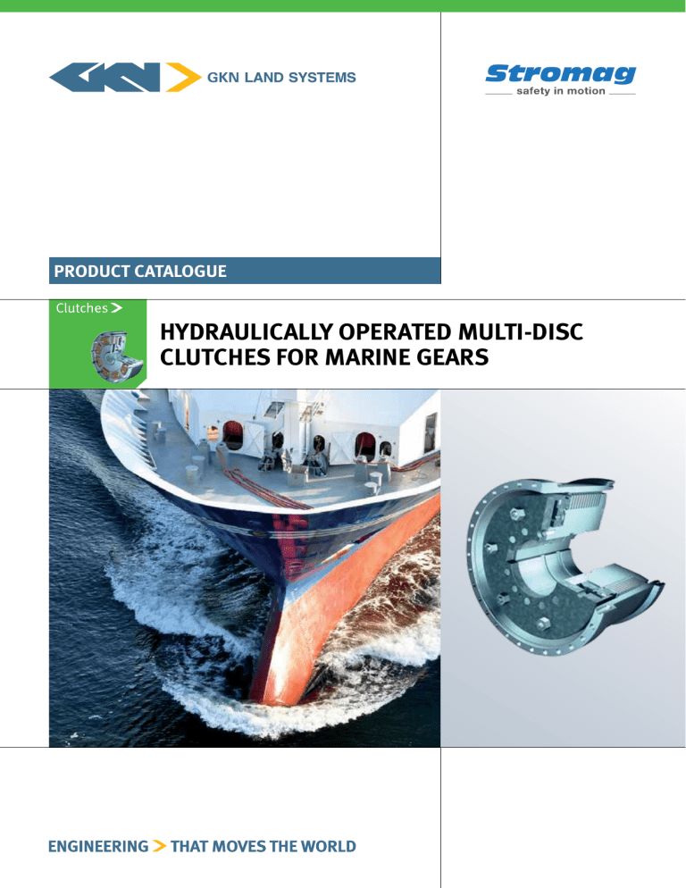
Product catalogue Hydraulically operated multi-disc clutches for marine gears Intergrated Powertrain components, Systems and Solutions Couplings Clutches Gearboxes Driveshafts Brakes Controls Electric Wheels Catalogue No. D 228 This catalogue for hydraulically operated multi-disc clutches for marine gears cancels and replaces all former editions. We reserve the right to modify the dimensions and constructions. GKN Stromag products comply with the Quality Standard to DIN ISO 9001. Content > > Multi-disc clutches KMS / KMS...AV / KMS...THC > Construction and Function > Hints to the construction > Switching processes > Cooling oils for coupling types KMs And KMs...Av > Selection of the clutch size > Examples of assembly 4 5 7 8 13 Hydraulically operated multi-disc clutches for marine gears Multi-disc clutch KMS / KMS...AV / KMS...THC Hydraulically operated multi-disc clutches for marine gears They are used everywhere large torques must be transferred reliably in the smallest of spaces. Setting the trend for GKN Stromag development work is the „No Limit“ (KMS 200,000). With a rated torque of over 2,000,000 Nm, a diameter of 1.2 m, and a weight of nearly 4 t, it is one of the largest and most powerful clutches on the entire drive sector. Benefits include > Very favorable ratio torque / weight > Low mass moment of inertia > High heat load capacity > Dissipation of the switching heat by oil inner cooling > Long lifetime of the discs > Less maintenance work, possible disc wear is balanced automatically by the piston stroke > Remote control capability > Infinitely variable increase of the oil pressure and consequently switching without shocks > Mechanical emergency switching device in case of failure of the pressure oil supply Type specific advantages KMS...THC > KMS > KMS...AV > > Switching heat dissipated by internal oil cooling > Switching heat dissipated by internal oil cooling > Integrated in the gears > Integrated in the gears > Clutch housing on bearings for applications outside of the gears > For large shaft diameters >Higher thermal load capacity for the same torque as KMS > Clutch in protective closed housing For large torques For high thermal loads With external cardan shaft connection > No internal oil cooling necessary > Direct connection e.g. of a PTO to the clutch housing 4 CONSTRUCTION AND FUNCTION The pressure oil is led to the cylinder space of the clutch through a bore in the shaft. Thereby the piston presses the disc pack against the pressure disc and closes the clutch. Due to the consequently occurring friction tightness between the inner discs and the outer discs a torque can be transmitted from the inner body to the outer body. When blocking the pressure oil, the torque transmission is terminated, the cylindrical pressure springs set the piston to its release position. The clutch is disengaged. The inner discs are made of steel and have spring effect. They separate the single discs precisely. If the technical constraints require internal oil cooling (KMS, KMS…AV), the outer multi-discs feature a special sintered bronze lining and a special surface geometry that under high thermal load can convey enough cooling oil from the inside to the outside through the multi-disc package. The heat generated by friction can then be absorbed and transported away. HINTS TO THE CONSTRUCTION The clutches are provided with a mechanical emergency switching device. The emergency screws at the cylinder must be easily accessible. In order to avoid oil leakage loss it is necessary to maintain the shaft fit m6 or n6 besides the clutch fit H7. The clutch outer body must be duly bearinged with connection part and must be fixed axially like the clutch inner body. All screws are secured by liquid loctite. In order to prevent reduction of the clutch torque, use only oils without friction coefficient reducing material (additives). The oil viscosity depends on the technical conditions. For further details see chapter “cooling oils”. The hydraulic conducts must be dimensioned in compliance with the working volume of the clutch and the cable length. Avoid sharp bends in the cables. Insufficiently dimensioned cables deteriorate the switching behavior. The cooling oil conducts as well must be sufficiently dimensioned to assure an optimum cooling of the disc pack. A small amount of leakage oil penetrates with the metal piston rings we use. This has to be taken into consideration when determining the pump output. For the hydraulic oil and cooling oil conduct through the shaft corresponding conduct facilities are required. These facilities can be located on the front side of the shafts or radial on the shaft. There is a variety of executions. In special cases please consult GKN Stromag AG. The axial oil conduct is leakage-free. With the radial oil conducts a slight leakage oil flow occurs which has to be taken into consideration when dimensioning the pump output. 5 Hydraulically operated multi-disc clutches for marine gears Generally the leakage oil quantity of the clutch and the oil conduct depends on the size, production tolerances, pressure, oil viscosity and temperature. Please inquire the details for the particular application case. Hydraulic connection Cooling oil Bronze Fix free from distortion Fix free from distortion Hydraulic connection radial oil conduct Cooling oil Bronze Hydraulic connection axial oil conduct Cooling oil 6 Switching processes Switching the multi-disc clutch under a differential speed places a high mechanical and thermal load on the clutch in addition to applying the clutch torque to the connected drive elements (shafts, gear teeth, other clutches, etc.). The buildup of switching pressure over time must therefore be introduced with care. The load on the clutch is tested during its configuration stages (see “Selection of the clutch size”). The user may have to conduct these tests on the other drive elements. There is a range of hydraulic components and actuating options for building up the switching pressure over time. For instance, proportional pressure control valves may be used. In principle, we recommend switching the clutch over two stages, i.e. a lower switching pressure that synchronises the powertrain under a low load. Then the pressure needs to be raised to the maximum operating value for the reliable transfer of the full drive power. COOLING OILS FOR COUPLING TYPES KMS AND KMS...AV Cooling oils serve for lubrication and heat dissipation of the frictional heat generated in the disc pack during braking and with idle run. The trouble-free operation – in particular the frictional behavior – strongly depends on the utilization of suitable oils. For gearboxes with multi-disc clutches sometimes a compromise is required: oils being favorable for a high gearwheel charge – special additives – can affect the frictional behavior of the multidisc clutch. Requirements to the cooling oil, special hints > High ageing and thermal stability > Good protection against corrosion > Neutral to usual sealing materials, paintings, non ferrous heavy metal and steel > Max. corrosion degree 2 DIN EN ISO 2160 > The alkaline setting must be less than TBN = 20 > No deposit of oil carbon > Additives must not affect considerably the frictional behavior. Grease lubricants such as MoS2 must not be used > EP- and HD-additives (CLP-/HLP-oils) reduce the friction coefficient > Usual viscosity range: 46…150 mm²/s, in special cases up to 220 mm²/s at 40°C > High viscosity affects the switching behavior, excessive idle run torque can occur We can provide you with a list of recommendations for your choice of suitable cooling oils and oil lubricants. On request, we can also test other oils at our location. However, special conditions of application may have negative effects on the friction behaviour. 7 Hydraulically operated multi-disc clutches for marine gears SELECTION OF THE CLUTCH SIZE In any case the determination of the clutch size should be carried-out by us. It is determined according to the torque to be transmitted and according to the occurring switching heat. On the basis of these data and considering the idle run heat the suitable cooling oil quantity can be calculated. It must correspond to the pertinent clutch size and to the technical conditions of the individual application case. 1. Determination of the required dynamic clutch torque TKdyn req. = KA x TAn TKdyn ≥ TKdyn req. TKdyn req. Required dynamic torque of the clutch TKdyn Available dynamic torque of the clutch TAn Minal torque of the prime mover, calculated from the nominal output and nominal speed KA Application factor (Without ice class factor), depending on: > Single- or multi-drive > Type of flexible coupling (damping) > Type of probeller or PTO For specific application cases the ice class factor has to be considered. Diesel connection by highly-flexible coupling Single-drive Multi-drive Fixed pitch propeller 1.4 1.5 Controllable pitch propeller 1.3 1.4 Waterjet-Propeller 1.5 1.6 PTO drive 1.4 1.5 2. Recalculation of the clutch in relation to the friction heat charge The clutch selected as per the torque shock factor KA has to be recalculated in relation to the occurring friction heat charge. If the admissible thermal load is not sufficient, a clutch with an accordingly higher admissible thermal load has to be selected, namely independent from the factor KA. 8 The following has to be taken into consideration > Engine type > Engine nominal output and -speed > Torque characteristic of the engine > Mass moment of inertia of the input side with engine (ahead of the clutch) > Clutch input speed at switching start > Switching strategy > Required acceleration time > Entire mass moment of inertia to be accelerated (gear and clutch parts, propeller shaft, propeller and water coefficient) > Load torque or load torque characteristic curve during the switching process > Switching frequency The heat requirements are calculated at our location with consideration to the limits specific to each clutch size. If you wish, we can issue you a findings report. 3. Determination of the admissible permanent alternating torque The clutch selected with torque shock factor KA must be recalculated with respect to the heat loads generated by friction. If the maximum thermal load is inadequate, a clutch must be selected with a higher thermal load limit, irrespectively of the factor KA. 3.1 To avoid tooth profile lifting-off With all conditions the permanent alternating torque must be less than the accordingly existing load torque to avoid lifting-off of the tooth profiles (no torque crossover). TKW < Tload Exception: Interruption free passing of the critical speed range 3.2 To avoid mechanical overloading TKW ≤ ± (KA - 1) x TAn (KA - 1) x TAn stellt den Unterschied zwischen TKdyn erf. Und TAn dar. Ein Wechseldrehmoment in dieser Größe belastet die Kupplungsverzahnung max. mit TKdyn erf., welches ≤ TKdyn ist. Damit wird die Verzahnung nicht überlastet. 4. Determination of the max. admissible clutch speed From case to case check the max. admissible speed of the clutch. Differ between: > Speed with closed clutch (comparison with nmax in the data sheet) > Speed with open clutch a) Innerbody (comparison with nmax in the data sheet) b) differential speed outer body/inner body (comparison with nrel in the data sheet) 9 Øa Ø b H7 Øg v n s t r min. max. Working vol. new state max. wear Mass moment of inertia inside outside Weight Cooling oil quantity 0.1 0.11 30 245 210 108 80 195 145 8 225 225 12xM10 12x8 145 135 59 104 17 24 12 15 10 6.5 kgm2 kgm2 kg a b c dmax e e1 l m n p q r s t v w f g h k2) j2) 0.175 0.17 40 270 235 120 90 215 160 8 250 250 12xM10 12x10 155 145 66 113 17 26 12 15 10 6.5 0.18 0.28 0.13 0.20 dm3 dm3 l/min l/min 2.7 2,600 3,400 5 15 2.7 8,000 800 q Øf 2,900 3,700 4 12 6,000 600 l m s Øf rpm rpm l m n s s p q w 1120 0.285 0.272 51 300 260 130 100 240 180 8 280 280 12xM10 12x12 165 155 70 117 19 28 12 15 10 8.5 0.19 0.31 2,500 3,100 6 19 2.7 11,200 w Ø d H7 Emergency engagement 0.400 0.300 55 330 290 145 115 270 210 10 310 310 12xM12 12x12 140 130 86 23 36 12 18 10 9.5 0.18 0.30 2,300 2,750 5 14 2.6 9,300 1600.1 1) Max rel. speed between inner and outer part considering the direction of rotation Øa p bar bar Øg Excess working pressure Spring return pressure nmax. Speed rel.1) Ø b H7 Nm r Øc Tdyn. Torque Clutch size KMS v t Øh Øh Threaded bore K Fitting key bore J Øc Diameter mm Lenght mm Ø e1 Ø e1 Ø d H7 Øe Øe 1600 0.521 0.445 72 330 290 145 115 270 210 10 310 310 12xM12 12x12 180 170 76 125 23 31 12 18 10 9.5 0.29 0.46 2,300 2,750 8 24 2.6 16,000 ° 120 ° 60 0.844 0.816 101 365 320 165 125 300 230 12 340 345 12xM14 12x16 195 185 81.5 134 25 33.5 15 21 10 9.5 0.37 0.59 2,000 2,500 10 30 2.7 22,500 2250 0.48 0.8 1,700 2,100 13 40 2.9 32,000 3200 2.7 2.23 190 455 405 220 165 380 300 14 430 430 18xM14 12x16 245 235 101 168 32 42 20 21 10 11.5 0.75 1.19 1,650 1,950 15 50 3 45,000 min. 25 3) 4500 4.76 4.1 269 505 455 250 190 428 340 16 480 485 18xM14 16x16 275 265 118 188 36 49 20 21 10 11.5 0.96 1.54 1,500 1,750 20 61 3 63,000 6300 8.03 6.36 360 560 500 280 210 470 370 16 530 530 18xM20 16x20 300 290 138 210 42 61 20 30 10 15 1.52 2.3 1,300 1,500 25 76 3 90,000 9000 Cone interference fit with feather key(s) 1.62 1.44 140 415 370 200 150 340 270 12 390 395 18xM12 12x16 220 210 93 150 27 39 15 21 10 9.5 Cooling oil conduct 13.95 9.5 480 620 550 310 235 524 420 18 585 585 24xM20 16x24 335 325 152 230 46 68 20 30 10 15 2.1 3.1 1,200 1,400 33 100 3 125,000 12500 OPTIONAL SHAFT-HUB CONNECTIONS > 2) Thread and fitting key bores are to be made by the customer 0.652 0.546 78 365 320 165 125 300 230 12 340 345 12xM14 12x16 151 141 92 25 40 15 21 10 9.5 0.24 0.40 2,000 2,500 6 18 2.7 13,100 2250.1 120 ° ° 60 oil conduct Pressure 31.5 22.95 770 745 665 370 280 630 490 20 705 705 18xM24 16x24 370 360 168 248 52 75 20 36 10 17 3.0 4.4 1,000 1,150 43 125 3 180,000 18000 63.4 41.5 1090 860 780 430 315 740 560 22 820 820 24xM24 16x24 376 366 165 240 55 82 20 36 10 21 3.7 4.8 850 1,000 52 158 3 260,000 25000.1 69.4 48.0 1190 860 780 430 315 740 560 22 820 820 24xM24 16x24 410 400 177 264 55 82 20 36 10 21 4.4 6.3 850 1,000 62 190 3 315,000 25000 50000 195.0 116.0 2210 1050 955 530 400 920 725 28 1000 1000 24xM30 16x30 510 500 224.5 320 69 104.5 20 45 10 21 7.7 11.4 650 840 105 310 2.8 500,000 3) Max. admissible 29 bar 117.0 69.8 1650 950 855 480 360 820 640 25 900 900 18xM30 16x30 470 460 208.5 300 63 96.5 20 45 10 21 6.0 8.5 750 900 85 250 3 360,000 36000 Involute spline fit (e.g. DIN 5480) Øg v n s Tdyn. Øc Øg Øa Øc min. max. Working vol. new state max. wear Mass moment of inertia inside outside Weight Cooling oil quantity Excess working pressure Spring return pressure nmax. Speed rel.1) Torque r Ø b H7 Cluch size KMS...AV v t r l m n p q r s t v w dmax e e1 f g h k2) j2) kgm2 kgm2 kg 1.55 1.57 148 415 370 165 120 340 270 12 390 395 18xM12 12x16 220 210 90.5 150 27 36.5 20 21 10 - 0.62 0.98 a b c 3200 32,000 dm3 dm3 l m s Øf 3 1,600 2,100 19 57 l m n s s p bar bar rpm rpm l/min l/min Nm t q Øf w 2.0 1.53 151 455 405 208 155 380 300 14 430 430 18xM14 12x16 190 180 115 32 50 20 21 10 11.5 0.48 0.77 2,5 1,400 1,950 12 35 26,000 4500.1 q w Ø d H7 Emergency engagement 4500 2.6 2.3 195 455 405 208 155 380 300 14 430 430 18xM14 12x16 245 235 110 168 32 42 20 21 10 11.5 0.9 1.4 2,5 1,400 1,950 20 60 45,000 1) Max rel. speed between inner and outer part considering the direction of rotation Øa p Øh Øh Threaded bore K Fitting key bore J Ø b H7 Diameter mm Lenght mm Ø e1 Ø e1 Ø d H7 Øe Øe ° 3.7 3.1 224 505 455 220 175 420 330 16 480 485 18xM16 12x16 225 215 105 142 36 45 20 24 10 11.5 0.79 1.2 2,6 1,350 1,750 18 54 44,000 6300.1 120 ° 60 120 ° ° 6.2 5.0 300 560 500 250 200 470 365 16 530 530 18xM20 12x20 247 237 155 42 70 30 30 10 15 1.1 1.6 2,6 1,150 1,600 22 64 60,000 9000.1 Cooling oil conduct 6.9 5.9 331 560 500 250 200 470 365 16 530 530 18xM20 12x20 274 264 120 182 42 50 30 30 10 15 1.3 2.0 2,6 1,150 1,600 27 80 75,000 min. 25 3) 9000.2 7.6 6.8 365 560 500 250 200 470 365 16 530 530 18xM20 12x20 300 290 139 210 42 57 30 30 10 15 1.6 2.5 2,6 1,150 1,600 32 96 90,000 9000 13.0 10.7 495 620 550 280 220 524 420 18 585 585 18xM24 12x24 355 345 152 250 46 62 30 36 10 15 2.3 3.5 2,8 1,000 1,400 40 120 125,000 12500 Cone interference fit with feather key(s) 18.1 12.7 520 700 620 310 245 592 460 20 660 660 18xM24 16x24 258 248 160 51 78 20 36 10 17 1.8 2.6 2,6 900 1,250 30 88 105,000 18000.1 OPTIONAL SHAFT-HUB CONNECTIONS > 2) Thread and fitting key bores are to be made by the customer 4.5 4.2 275 505 455 220 175 420 330 16 480 485 18xM16 12x16 275 265 116 188 36 47 25 24 10 11.5 1.2 1.9 2,6 1,350 1,750 26 80 66,000 6300 60 oil conduct Pressure 61.0 40.4 1,115 860 780 400 300 722 560 22 820 820 24xM24 16x24 375 365 165 240 55 70 35 36 10 21 3.5 4.9 2,6 700 1,000 60 183 260,000 25000.1 3) Max. admissible 29 bar 23.5 19.2 580 700 620 310 245 592 460 20 660 660 18xM24 16x24 330 320 174 233 51 68 20 36 10 17 3.3 4.7 2,6 900 1,250 50 150 180,000 18000 66.8 46.3 1,220 860 780 400 300 722 560 22 820 820 24xM24 16x24 410 400 180 275 55 78 35 36 10 21 4.2 6.2 2,6 700 1,000 72 220 315,000 25000 Involute spline fit (e.g. DIN 5480) 50000 152 107.5 1,970 970 876 450 320 860 650 25 920 940 36xM30 535 486 223 360 68 98 24 48 49 - 7.6 12.7 2,7 600 900 105 320 500,000 y 1.28 2,100 2,500 0.035 0.065 0,027 0,094 N 40 x 2 x 18 28 185 150 130 90 j6 63 35 H7 36 H9 45 H7 130 187 2 25 44 111 10.5 33.5 72.5 8xM12 12xM8 bar bar rpm rpm dm3 dm3 kgm2 kgm2 l n o p q r s t u v w g h j k d e f kg a b c 1,400 Nm 140 Gew.-Bohr. Threaded bore ww Øk Øi 240 0.050 0.101 1.08 1,900 2,400 2,400 0,037 0,18 N 50 x 2 x 24 39 214 175 155,5 110 j6 75 45 H7 46 H9 55 H7 165 205.5 2.5 30 50 110 17.5 27.5 71 8xM14 12xM8 Ø h H7 Øl 1) Max relative speed between inner and outer part with consideration to sense of rotation Threaded bore Tdyn. Excess working pressure Spring return pressure nmax. Speed rel.1) Working vol. new state max. wear Mass moment of inertia inside outside Gearing DIN 5480 Weight Clutch sizee KMS...THC Torque Diameter mm Lenght mm u r Øm s n 0.060 0.099 1.7 1,900 2,400 3,700 370 q 0,072 0,251 N 65 x 3 x 20 48 231 190 155,5 110 j6 85 55 H7 59 H9 70 H7 180 215.5 2.5 30 50 120 17.5 33.5 75 10xM16 12xM8 t y Verzahnung Gearing (DIN 5480) Øg p Emergency Notschaltung Øf Øc Ød Øe 690 0.111 0.222 2.68 1,900 2,300 6,900 Øb 0,21 0,7 N 80 x 3 x 25 85 290 250 218 140 j6 112 70 H7 74 H9 85 H7 140 195 244 F7 228 5 30 65 120 19 33.5 73 8xM18 8xM12 min. 27 2) o Gew.-Bohr. v Threaded engagement Øa 990 0.179 0.313 3.01 1,900 2,300 9,900 1400 0,71 3,17 N 100 x 3 x 32 184 405 340 280 175 j6 147 90 H7 94 H9 110 H7 220 365 325 H7 278 6 38 70 155 22.5 43.5 94.5 8xM22 12xM16 0.184 0.406 3.99 1,900 2,300 14,000 2) Max. admissible 29 bar 0,436 1,105 N 90 x 3 x 28 111 330 280 245 175j6 116 75 H7 84 H11 100 H7 210g6 270 250 245 6 32 70 130 14.5 39.5 81.5 8xM20 12xM12 bore v 2250 1,37 5,20 N 130 x 3 x 42 252 455 390 345 250j6 168 120 H7 124 H11 140 H7 220 300 275H7 313 5 42 90 160 21.5 43.5 100.5 10xM24 12xM16 0.293 0.586 4.01 1,900 2,300 22,500 Example of Assembly > Hydraulically operated multi-disc clutch KMS 18000 arranged on the gear output side. Drive of a double-hull hight-speed ferry through gas turbines (2 x port, 2 x starboard, master and slave each) and one double-reduction gear each on 4 water jets. Clutch Water jet MSCC GT1 GT2 Water jet Clutch 13 Hydraulically operated multi-disc clutches for marine gears Hydraulically operated multi-disc double clutch KMS 50000 as special execution with small outer diameter (short axle distance enginepropeller shaft) in the main gear of a shuttle tanker. Further multi-disc KMS for connection os auxiliary drives. PTO Pumps Engine PTO Generator Propeller Hydraulically operated multi-disc clutch KMS 14 Hydraulically operated multi-disc clutch KMS mounted within a gearwheel in a marine main gearbox. Generator Diesel engine to Propeller Hydraulically operated multi-disc clutch KMS 9000 externally located on the main gear of a RO-RO container cargo vessel with double engine system. Engine Clutch Propeller Engine Clutch PTO 15 GKN Land Systems© 2014 PO Box 55, Ipsley House, Ipsley Church Lane, Redditch, Worcestershire B98 0TL P: +44 (0)1527 517 715 Couplings Clutches Gearboxes Driveshafts Brakes Controls Electric Wheels GKN Stromag AG Hansastraße 120 59425 Unna P: +49 2303 102-0 F: +49 2303 102-201 www.gknlandsystems.com info.stromag@gkn.com Find out more about GKN Stromag global trade representatives GKN LS 37 GB 0914 FL 1 -0,25 The GKN Stromag AG is a company of GKN Land Systems
