Solutions
For Business-Critical Continuity™
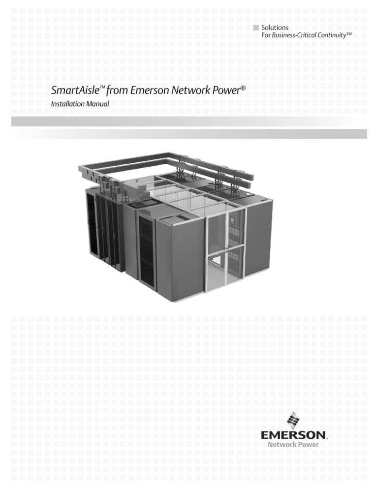
SmartAisle™ from Emerson Network Power®
Installation Manual
TABLE OF CONTENTS
1.0
INTRODUCTION . . . . . . . . . . . . . . . . . . . . . . . . . . . . . . . . . . . . . . . . . . . . . . . . . . . . . . . . . .1
1.1
SmartAisle Configuration . . . . . . . . . . . . . . . . . . . . . . . . . . . . . . . . . . . . . . . . . . . . . . . . . . . . . 1
1.1.1
Typical SmartAisle Composition . . . . . . . . . . . . . . . . . . . . . . . . . . . . . . . . . . . . . . . . . . . . . . . . . 1
1.2
Safety Considerations . . . . . . . . . . . . . . . . . . . . . . . . . . . . . . . . . . . . . . . . . . . . . . . . . . . . . . . . 1
2.0
ROOM PREPARATION AND INSTALLATION CONSIDERATIONS . . . . . . . . . . . . . . . . . . . . . . . . .2
2.1
Mark Floor for Equipment Installation . . . . . . . . . . . . . . . . . . . . . . . . . . . . . . . . . . . . . . . . . . 2
2.1.1
Floor Marking Requirements. . . . . . . . . . . . . . . . . . . . . . . . . . . . . . . . . . . . . . . . . . . . . . . . . . . . 3
2.2
Overhead Clearances . . . . . . . . . . . . . . . . . . . . . . . . . . . . . . . . . . . . . . . . . . . . . . . . . . . . . . . . . 3
2.3
Rear Clearance Requirements . . . . . . . . . . . . . . . . . . . . . . . . . . . . . . . . . . . . . . . . . . . . . . . . . . 4
2.4
Equipment Preparation . . . . . . . . . . . . . . . . . . . . . . . . . . . . . . . . . . . . . . . . . . . . . . . . . . . . . . . 4
2.4.1
2.4.2
Gaskets . . . . . . . . . . . . . . . . . . . . . . . . . . . . . . . . . . . . . . . . . . . . . . . . . . . . . . . . . . . . . . . . . . . . . 4
Blanking Panels—Fill Open Sections of Racks. . . . . . . . . . . . . . . . . . . . . . . . . . . . . . . . . . . . . . 4
2.5
Tools Required—Aisle Containment Only . . . . . . . . . . . . . . . . . . . . . . . . . . . . . . . . . . . . . . . . 4
3.0
INSTALLATION . . . . . . . . . . . . . . . . . . . . . . . . . . . . . . . . . . . . . . . . . . . . . . . . . . . . . . . . . .5
3.1
Installation Order. . . . . . . . . . . . . . . . . . . . . . . . . . . . . . . . . . . . . . . . . . . . . . . . . . . . . . . . . . . . 5
3.2
Preliminary Steps in Containment Solution Installation . . . . . . . . . . . . . . . . . . . . . . . . . . . . 6
3.3
Busway and Bracket Installation . . . . . . . . . . . . . . . . . . . . . . . . . . . . . . . . . . . . . . . . . . . . . . . 6
FIGURES
Figure 1
Figure 2
Figure 3
Figure 4
Figure 5
SmartAisle design example . . . . . . . . . . . . . . . . . . . . . . . . . . . . . . . . . . . . . . . . . . . . . . . . . . . . . . . .
Overhead clearances . . . . . . . . . . . . . . . . . . . . . . . . . . . . . . . . . . . . . . . . . . . . . . . . . . . . . . . . . . . . . .
Installation order, example . . . . . . . . . . . . . . . . . . . . . . . . . . . . . . . . . . . . . . . . . . . . . . . . . . . . . . . .
Bus bracket orientation . . . . . . . . . . . . . . . . . . . . . . . . . . . . . . . . . . . . . . . . . . . . . . . . . . . . . . . . . . .
Completed installation example. . . . . . . . . . . . . . . . . . . . . . . . . . . . . . . . . . . . . . . . . . . . . . . . . . . . .
i
2
3
5
6
7
ii
Introduction
1.0
INTRODUCTION
The SmartAisle from Emerson Network Power is an intelligent row-based system that integrates
data center racks, power, row cooling, aisle containment, monitoring and control technologies into a
complete data center layout.
SmartAisle places row-based Emerson equipment in new data center installations or self-contained
expansions in existing facilities. The design incorporates the capacities of cooling units and power
distribution equipment for optimal operation and performance.
Spacing, dimensions and layout in a Smart Aisle layout are exact. The floor plan must be followed
exactly for proper installation and operation.
1.1
SmartAisle Configuration
Each SmartAisle from Emerson is custom-designed, offering the most favorable layout for the
installation. The design takes into account the equipment required, equipment sizes (with the heat
load and/or power consumption), cooling equipment type (air-cooled, chilled water or water/glycol
based) and whether cooling or power redundancy is desired.
1.1.1
Typical SmartAisle Composition
Each SmartAisle from Emerson will be unique, owing to the installation’s mission, room layout and
other considerations. Some typical components are:
•
•
•
•
•
•
•
•
Liebert APM™
Liebert Battery Cabinets
Liebert BDC™
Liebert CRV™
DCF™ or DCM™ Cabinets
Modular Containment
Liebert MB™
Liebert PDU’s
Depending on heat load and power requirements, there may be multiple Liebert Precision Cooling
units and multiple AC Power Protection and Distribution units.
This document provides an overview and& guidelines to comprehensive system installation.
Individual equipment user and installation manuals are required for complete and proper
installation. The required manuals ship with the equipment and are available at the Liebert Web
site: www.liebert.com
1.2
Safety Considerations
Refer to the manual for each unit that will be installed in your SmartAisle for detailed warnings and
cautions.
1
SmartAisle® from Emerson Network Power®
Room Preparation and Installation Considerations
2.0
ROOM PREPARATION AND INSTALLATION CONSIDERATIONS
The installation area should be cleared of any debris and the floor cleaned to permit marking for
equipment installation. Equipment and lifting equipment should be arranged for easy installation,
either in the room or in an adjacent area where it is readily accessible.
The floor must be level. The ceiling must be high enough to accommodate the racks and Liebert MB’s
required to supply power to the racks equipment.
2.1
Mark Floor for Equipment Installation
Marking the floor as shown on the SmartAisle layout will ease installation. The floor can be marked
with tape, pencil or another marking method. An example is shown in Figure 1.
NOTE
Whatever marking method is used, the floor must be marked exactly as shown in the
SmartAisle layout.
Figure 1
SmartAisle design example
Service and Airflow Clearance
(varies by equipment type)
10mm spacing is
required for Roof
Panel installation
Equipment
(Width
Varies)
.39"
(10mm)
Equipment
(Width
Varies)
.39"
(10mm)
Equipment
(Width
Varies)
Equipment
(Width
Varies)
.39"
(10mm)
Equipment
(Width
Varies)
.39"
(10mm)
Aisle Width
4' or 6' (1219mm or 1829mm)
Depends on clearance
requirements and Liebert
SmartAisle components
Aisle width must be
measured from the frame of
a piece of equipment, such
as a rack or UPS, to the
frame of the equipment
directly across the aisle. The
aisle width is critical for
installing Roof Panels .
Do not measure the aisle
width from door to door.
Equipment
(Width
Varies)
.39"
(10mm)
Equipment
(Width
Varies)
.39"
(10mm)
Equipment
(Width
Varies)
Equipment
(Width
Varies)
.39"
(10mm)
.39"
(10mm)
Service and Airflow Clearance
(varies by equipment type)
SmartAisle® from Emerson Network Power®
2
Equipment
(Width
Varies)
Room Preparation and Installation Considerations
2.1.1
Floor Marking Requirements
The SmartAisle layout will show the equipment arrangement and the spacing for each unit. The
design must be transferred to the floor installation exactly as shown.
•
•
•
•
•
2.2
Corners must be 90-degree angles
Rows must begin at the same point
Rows must be parallel
Rows must be the same length
Row equipment must be spaced 10mm apart for proper alignment
Overhead Clearances
Some equipment used in the SmartAisle will have overhead clearances, such as for pipe entry or for
cooling air flow. Refer to the user manual for the equipment to determine the overhead clearance.
Below are overhead clearances for some of the equipment used in the SmartAisle.
• Modular Roof Panels: Modular Roof Panels attach to roof headers along the front of the row
equipment. If cable trays are used in the application, allow 3" (76mm) clearance above the rack
for the Modular Roof Panels.
• Liebert MB™: A Liebert MB busway can be mounted directly on a DCF™ or DCM™ rack; or
suspended from the ceiling. When suspended from the ceiling, the supporting member must be
strong enough to support the weight of the busway assembly. Refer to the installation
instructions supplied with the Liebert MB for specific requirements.
When attached directly to a Emerson rack, the Liebert MB can be configured in single-bus or
dual-bus arrangements. A single-bus installation requires 13.38" (339.9mm) clearance above the
rack, and a dual-bus requires 23.56" (598.4mm) clearance above the rack.
• Liebert APM™: Emerson® recommends 24" (610mm) overhead clearance for cooling air flow.
Figure 2
Overhead clearances
3
SmartAisle® from Emerson Network Power®
Room Preparation and Installation Considerations
2.3
Rear Clearance Requirements
Clearance at the rear of the aisle will usually match the width of the contained aisle (e.g. 4ft or 6ft.
(1219mm or 1829mm). When rear clearance equal to the contained aisle is not possible, the
installation should follow these guidelines:
• The Liebert CRV™ Precision Cooling unit requires a minimum of 25.56" (64.9mm) rear service
clearance if positioned between server racks. The unit requires 39.31" (998.5mm) rear service
clearance if positioned directly against a wall.
• The Liebert APM™ UPS requires a minimum of 12" (305mm) rear airflow clearance. The unit
requires 36" (914mm) in the front for service access.
Other Emerson equipment may have bigger or smaller clearance requirements; refer to the
installation instruction in each unit’s user manual.
2.4
Equipment Preparation
Certain pieces of Emerson equipment require particular installation steps. Being familiar with
installation of each piece of will make completion easier. Generally, equipment should not be installed
until overhead obstructions have been checked for interference with equipment installation. Piping
and electrical connections should be made after all SmartAisle components have been installed.
2.4.1
Gaskets
Factory-supplied gaskets must be applied to one side of each unit in the row to prevent air leaks that
could prevent proper cooling airflow. When the first unit is set in place, a foam gasket must be applied
to the outer side of the unit—the side that will be against the next unit installed.
Emerson racks will be connected with factory-supplied hardware that ensures proper spacing. Units
such as a Liebert CRV or Liebert APM must be placed 0.39 in. (10mm) away from the adjacent unit.
Once the spacing has been set at 0.39 in. (10mm), the gap can be maintained by inserting a
containment spacer between the Liebert CRV or Liebert APM and the adjacent unit.
2.4.2
Blanking Panels—Fill Open Sections of Racks
Open areas in racks must be blocked to promote proper cooling air flow through the rack equipment.
Many of these areas can be filled by proper equipment installation. Where open areas in a rack
remain, they must be closed with blanking panels or similar devices. Contact your local Emerson®
sales representative to obtain blanking panels.
2.5
Tools Required—Aisle Containment Only
•
•
•
•
•
•
•
•
Tape Measure
Masking tape or chalk line
Carpenter's bubble level or laser level
Adjustable wrench
11/16" wrench
5/16" socket or nut driver
3/8" drill
Step ladder
NOTE
Additional tools will be required for installing the equipment within the SmartAisle, such as
the Liebert CRV, Liebert APM and racks.
SmartAisle® from Emerson Network Power®
4
Installation
3.0
INSTALLATION
3.1
Installation Order
Any piece of row equipment may be installed first. Installation may be eased by installing the
equipment that is farthest from the room entrance. Use lifting equipment, if required, to place the
first piece of equipment on its marked position. Follow the floor markings made from the SmartAisle
drawings to place the remaining equipment.
Equipment installation in the first row may begin at either end of the row, but it will be easier if work
begins at the end of a row and proceeds incrementally (see Figures 2 and 3). In this example, the
unit at either end of either row may be installed first. If the unit labeled #1 is installed first, work in
the row should proceed in numerical order to #5. If the unit labeled E is installed first, work in the
row should proceed in reverse order to the unit labeled A.
Installation will be easier if work begins in an area that will become less accessible to lifting
equipment, such as a forklift, as row equipment is added.
All equipment on each side of the aisle must be adjusted to the same height to ensure efficient cooling
air containment. Aisle height can be adjusted with either leveling feet or spacers. After all units on
one side row have been installed, leveled and properly aligned, work may proceed to the next row.
Figure 3
Installation order, example
1
2
3
4
5
D
E
Row 1
One side of each unit
will require a gasket.
Row 2
A
B
C
Drawing not to Scale
(10mm Gap Between
Cabinets; Filled with Gaskets)
5
SmartAisle® from Emerson Network Power®
Installation
3.2
Preliminary Steps in Containment Solution Installation
Containment installation should follow installation and connection of the row-based equipment. For
detailed procedures, refer to the containment solution installation guide.
Containment Roof Extrusion Headers should be installed with spacers as needed. The bolts should be
left loose to be so the headers can be adjusted.
With Roof Headers in place, Door Headers should be placed to provide an alignment guide for the
containment doors. The doors may not glide smoothly until all headers are aligned and secured.
Laying Roof Panels in place will ease overall alignment.
Doors and Roof Panels should be removed and set aside to prevent interference and damage during
the rest of the installation.
3.3
Busway and Bracket Installation
A Liebert MB™ bracket should be installed on every other rack with the orientation shown in
Figure 4. The bus brackets may be moved later. Bus hangers can be set but may be moved later to
improve alignment.
Figure 4
Bus bracket orientation
Rack-Mount
Bus Brackets
Rack-Mount
Bus Brackets
SmartAisle® from Emerson Network Power®
6
Installation
! WARNING
Risk of electric shock. Can cause equipment damage, injury and death.
Before beginning to install the Liebert MB™, ensure that input power connections are locked
out and tagged out. Only properly trained and qualified personnel should install Liebert
busway components.
To ensure the proper installation and continued safe operation of the Liebert MB, refer to the
instructions supplied with the Liebert MB.
The Liebert MB should be assembled after all Bus Brackets and Hangers are securely installed.
Emerson recommends assembling the busway in sections short enough to handle safely.
Sections can be assembled on the floor, then moved to their final location. For ease of installation, the
busway section that spans the aisle can be installed after all above-rack bus is in place.
Generally, Bus Brackets or Hangers can be installed at approximately 5’ (1524mm) intervals.
Maximum distance between Bus Bracket or Hanger support points must not exceed 10’ (3048mm).
Refer to the instructions supplied with the Liebert MB.
After containment is secured, your SmartAisle from Emerson is ready for conventional electrical and
mechanical installation and connections, such as power and piping connections.
Figure 5
Completed installation example
7
SmartAisle® from Emerson Network Power®
Ensuring The High Availability
Of Mission-Critical Data And Applications.
Emerson Network Power, a business of Emerson (NYSE:EMR),
is the global leader in enabling Business-Critical Continuity™
from grid to chip for telecommunication networks, data centers,
health care and industrial facilities. Emerson Network Power
provides innovative solutions and expertise in areas including
AC and DC power and precision cooling systems, embedded
computing and power, integrated racks and enclosures,
power switching and controls, infrastructure management,
and connectivity. All solutions are supported globally by local
Emerson Network Power service technicians. Liebert AC power,
precision cooling and monitoring products and services
from Emerson Network Power deliver Efficiency Without
Compromise™ by helping customers optimize their data center
infrastructure to reduce costs and deliver high availability.
Technical Support / Service
Web Site
www.liebert.com
Monitoring
liebert.monitoring@emerson.com
800-222-5877
Outside North America: +00800 1155 4499
Single-Phase UPS & Server Cabinets
liebert.upstech@emerson.com
800-222-5877
Outside North America: +00800 1155 4499
Three-Phase UPS & Power Systems
800-543-2378
Outside North America: 614-841-6598
Environmental Systems
800-543-2778
Outside the United States: 614-888-0246
Locations
United States
1050 Dearborn Drive
P.O. Box 29186
Columbus, OH 43229
Europe
Via Leonardo Da Vinci 8
Zona Industriale Tognana
35028 Piove Di Sacco (PD) Italy
+39 049 9719 111
Fax: +39 049 5841 257
Asia
29/F, The Orient Square Building
F. Ortigas Jr. Road, Ortigas Center
Pasig City 1605
Philippines
+63 2 687 6615
Fax: +63 2 730 9572
While every precaution has been taken to ensure the accuracy
and completeness of this literature, Liebert Corporation assumes no
responsibility and disclaims all liability for damages resulting from use of
this information or for any errors or omissions.
© 2010 Liebert Corporation
All rights reserved throughout the world. Specifications subject to change
without notice.
® Liebert is a registered trademark of Liebert Corporation.
All names referred to are trademarks
or registered trademarks of their respective owners.
SL-11398_REV1_01-13
Emerson Network Power.
The global leader in enabling Business-Critical Continuity™
AC Power
Connectivity
Embedded Computing
Embedded Power
DC Power
Infrastructure Management & Monitoring
Outside Plant
Power Switching & Controls
Precision Cooling
EmersonNetworkPower.com
Racks & Integrated Cabinets
Services
Surge Protection
Emerson, Business-Critical Continuity, Emerson Network Power and the Emerson Network Power logo are trademarks of Emerson Electric Co. or one of its affiliated companies.
©2010 Emerson Electric Co.

