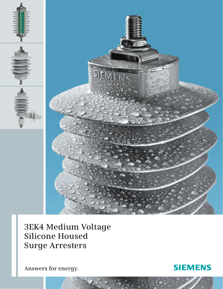
3EK4 Medium Voltage
Silicone Housed
Surge Arresters
Answers for energy.
3EK4 Optimum Performance
thanks to the unique Cage Design™
3EK4 – Housing Sizes (IEC)
B
C
F
J
K
Your benefits at a glance
2
■
Superior
The 3EK4’s superior electrical and
mechanical performance-to-weight ratio
is setting entirely new standards
■
Safe
The 3EK4’s proven Cage Design™
provides outstanding performance
in safety issues
■
Long-lasting
With its high-quality directly molded
silicone housing, the 3EK4 surge
arrester features prevention of partial
discharges and ultimate protection
against moisture ingress for a long
service life
M
R
3EK4 Cage Design™
M12 stainless steel stud
Nut, washer, stainless steel
Standard clamp, stainless steel
Stainless steel end cap
End fitting
Silicone housing,
directly molded
Metal oxide varistor (MOV)
FRP* rods
End fitting
Stainless steel end cap
Nut, washer, stainless steel
M12 stainless steel stud
■
Best Protection Choice
The 3EK4 surge arresters from Siemens
offer the best choice for the protection
against power surges in mediumvoltage distribution systems. Its ratings
are suitable for system voltages (Um)
up to 40.5 kV.
■
Superior Design
The 3EK4’s most innovative feature is
the Siemens Cage Design™: Preloaded
fibre-reinforced plastic rods are used
for high mechanical strength and
optimized performance-to-weight
ratios.
The Cage Design™ also features
a directly moulded silicone rubber
housing. The silicone is vulcanized
directly onto the metal oxide varistor
(MOV) blocks by using hightemperature and high-pressure
injection moulding; this effectively
eliminates partial discharges and
moisture ingress.
■
*FRP: Fibre-reinforced plastic
Superior Quality
The high-quality UV-resistant silicone
rubber is hydrophobic and repels
water and any pollution. It is resistant
to ozone, all common organic and
inorganic solvents and cleaning agents.
This results in excellent pollution
handling characteristics without any
ageing effects. It makes the 3EK4
perfect for applications in any
environment including industrial,
coastal or desert areas. The MOV blocks
used provide excellent residual voltage
values for lightning and switching
impulses to protect distribution
transformers. Additionally they also
do not suffer from ageing effects.
This makes the 3EK4 surge arrester
a long-lasting asset with lowest
life-cycle costs.
■
Superior Safety
Siemens believes that safety is
paramount. This is why a silicone
rubber housing is used which is flameretardant and self-extinguishing.
Further the content of combustible
material in the fibreglass structure has
been mimized so that any fire hazard is
reduced to an absolute minimum.
The 3EK4 surge arrester has also been
extensively type tested. Notably it has
passed the short circuit type test
according to Edition 2.1 of IEC 60099-4.
In this test the surge arrester has
successfully demonstrated its safe
behavior under realistic fault conditions
using the so called pre-failing method
(no use of fuse wires). The 3EK4
ensures the safety of personnel,
the public and the network.
3
3EK4 Surge Arresters According to IEC 60099-4
Nominal discharge current In
8/20 μs
10 kA
Line discharge class (LDC)
1
Maximum continuous operating voltage Uc
28.8 kV
Rated voltage Ur
36 kV
Long duration current impulse
2 ms
325 A
High current pressure relief
20 kA
Low current pressure relief
600 A
High-current impulse
4/10 μs
100 kA
Specified long-term load SLL (Mstat)
175 Nm
Specified short-term load SSL (Mdyn)
250 Nm
Energy absorption capability (thermal)
3.5 kJ/kVr
Table 1: 3EK4 surge arrester general technical data
Highest voltage
for equipment Um
Rated lightning impulse
withstand voltage
Solidly earthed
neutral system
Isolated
neutral system
Impedance earthed
neutral system
Resonant earthed neutral
system
[kV]
[kV]
2.75
30; 45; 60
3EK4 030-.C..
3EK4 060-.C..
3EK4 030-.C..
3EK4 060-.C..
3.6
20; 40
3EK4 030-.C..
3EK4 060-.C..
3EK4 030-.C..
3EK4 060-.C..
5.5
45; 60; 75
3EK4 060-.C..
3EK4 090-.C..
3EK4 060-.C..
3EK4 090-.C..
7.2
40; 60
3EK4 060-.C..
3EK4 090-.C..
3EK4 090-.C..
3EK4 090-.C..
8.25
60; 75; 95
3EK4 090-.C..
3EK4 120-.C..
3EK4 090-.C..
3EK4 120-.C..
12
60; 75; 95
3EK4 090-.C..
3EK4 150-.C..
3EK4 120-.C..
3EK4 150-.C..
15.5
75
3EK4 120-.C..
–
3EK4 150-.C..
–
15.5
85; 110
3EK4 120-.C..
3EK4 210-.C..
3EK4 150-.C..
3EK4 210-.C..
17.5
75
3EK4 150-.C..
–
3EK4 180-.C..
–
17.5
95
3EK4 150-.C..
3EK4 220-.C..
3EK4 180-.C..
3EK4 220-.C..
24
95
3EK4 210-.C..
–
3EK4 240-.C..
–
24
125; 145
3EK4 210-.C..
3EK4 300-.C..
3EK4 240-.C..
3EK4 300-.C..
25
125; 145
3EK4 210-.C..
3EK4 315-.C..
3EK4 250-.C..
3EK4 315-.C..
27
95
3EK4 210-.C..
–
3EK4 270-.C..
–
27
125
3EK4 210-.C..
–
3EK4 270-.C..
–
27
150
3EK4 210-.C..
3EK4 360-.C..
3EK4 270-.C..
3EK4 360-.C..
30
160
3EK4 240-.C..
–
3EK4 300-.C..
–
36
145
3EK4 300-.C..
–
3EK4 360-.C..
–
36
170
3EK4 300-.C..
–
3EK4 360-.C..
–
38
125
3EK4 300-.C..
–
–
–
38
150
3EK4 300-.C..
–
–
–
38
200
3EK4 300-.C..
–
–
–
40.5
190
3EK4 315-.C..
–
–
–
Table 2: Typical 3EK4 surge arresters for system voltages according to IEC 60099-4
4
Voltage per Unit [V/Ur]
1.25
Preheating to 40 °C
Preheating to 60 °C and stressed with
one high current impulse (100 kA 4/10 µs)
prior to temporary over-voltage (TOV)
1.20
1.15
1.10
1.05
1.00
0.95
0.90
0.85
0.80
0.1
1
10
100
1000
Time in seconds
Table 3: IEC power-frequency voltage vs. time (U-t) characteristic
Rated
voltage Ur
Continuous
operating
voltage Uc
Part number
Maximum values of the residual voltages
Flashover
at discharge currents of the following impulses distance
8/20 µs
1 kA
[kV]
8/20 µs
5 kA
[kV]
8/20 µs
10 kA
[kV]
8/20 µs
20 kA
[kV]
30/60 µs
500 A
[kV]
[mm]
Housing
insulation
Lightning
Power
impulse
frequency
withstand withstand
voltage
voltage
1.2/50 µs 1 min., wet
[kV]
[kV]
[kV]
[kV]
3
2.4
3EK4 030-1CB3
6.5
7.4
8.0
9.1
6.1
98
57
6
4.8
3EK4 060-1CB3
13.0
14.8
15.9
18.3
12.2
98
9
7.2
3EK4 090-1CC3
19.6
22.2
23.9
27.4
18.4
12
9.6
3EK4 120-1CC3
26.1
29.6
31.8
36.6
15
12.0
3EK4 150-1CF4
32.6
37.0
39.8
18
14.4
3EK4 180-1CJ4
39.1
44.4
21
16.8
3EK4 210-1CJ4
45.6
22
17.6
3EK4 220-1CJ4
24
19.2
25
Height
Width
H
W
Creepage
Net
(see fig. 1) (see fig. 1) distance weight
[mm]
[mm]
[mm]
[kg]
24
96
92
225
0.8
57
24
96
92
225
0.9
138
80
33
137
92
310
1.2
24.5
138
80
33
137
92
310
1.3
45.7
30.6
170
99
41
160
111
550
1.6
47.7
54.9
36.7
212
123
51
204
111
690
2.0
51.8
55.7
64.0
42.9
212
123
51
204
111
690
2.1
47.8
54.2
58.3
67.0
44.9
212
123
51
204
111
690
2.1
3EK4 240-1CK4
52.2
59.1
63.6
73.1
49.0
242
140
58
234
111
820
2.3
20.0
3EK4 250-1CK4
54.3
61.6
66.3
76.2
51.0
242
140
58
234
111
820
2.3
27
21.6
3EK4 270-1CM4
58.7
66.5
71.6
82.3
55.1
278
161
67
270
111
960
2.7
30
24.0
3EK4 300-1CM4
65.2
73.9
79.5
91.4
61.2
278
161
67
270
111
960
2.8
31.5
25.2
3EK4 315-1CM4
68.4
77.6
83.5
96.0
64.3
278
161
67
270
111
960
2.8
33
26.4
3EK4 330-1CR4
71.7
81.3
87.5
101.0
67.3
330
191
79
320
111
1.200
3.2
36
28.8
3EK4 360-1CR4
78.2
88.7
95.4
110.0
73.5
330
191
79
320
111
1.200
3.3
Table 4: 3EK4 part numbers and technical data (other voltages available on request)
5
3EK4 Accessories
3-D views for common design options
36
H*
36
M12
M12
Figure 2: 3EK4 surge arrester with accessories P12, P31 and M81
W*
Figure 1: 3EK4 surge arrester overall dimensions
* please refer to table 4
6
Figure 3: 3EK4 surge arrester with accessory P21
14.2
14.2
69.6
27
69.6
27
202
158.7
14
41
5
12.
5
12.
152
Figure 4: NEMA insulating bracket for Ur ≤ 15 kV
Figure 5: NEMA insulating bracket for Ur > 15 kV
Order code P12; 0.25 kg
Order code P12; 0.35 kg
17 26
50
50
17 26
14.5
12
156
14.5
91
91
20
20
108
12
14
44
41
44
200
Figure 6: DIN insulating bracket for Ur ≤ 15 kV
Figure 7: DIN insulating bracket for Ur > 15 kV
Order code P22; 0.85 kg
Order code P22; 1 kg
7
3EK4 Accessories
8
14.5
12
14
50
26
60
14
15
197
152
202
20
30
14
152
Figure 8: DIN metal bracket (hot dip galvanised)
Order code P21; 0.6 kg
Figure 9: NEMA metal bracket (hot dip galvanized), thickness 8 mm
Order code P11; 0.6 kg
75
37
16
13
25
4
14
0
5
33
13
20
12.
227
20
40
254
8
Figure 10: Mounting plate
Figure 11: L-bracket
Order code Q81; 1.6 kg
Order code M12; 0.1 kg
106
36
57
max.
15
61
Figure 12: Bird protection cap
Order code M81; 42 g
cable
8…
cable
14 …
14
18
M12
Figure 13: Line clamp
Figure 14: Disconnector
Order code M11; 0.1 kg
Order code P31; 0.1 kg
13.1
13.1
455
Figure 15: Insulated line/ground lead
Order code R51; 0.1 kg, conductor cross-section 16 mm2
9
Clearances
a
a
b
Figure 16: Clearances between surge arrester and earth
Ur
kV
a (center-center)
mm
b (center-ground)
mm
3
140
90
6
140
90
9
170
120
12
170
120
15
210
130
18
220
145
21
240
165
22
250
175
24
270
185
25
280
190
27
290
205
30
320
225
31.5
330
235
33
340
245
36
370
265
Table 5: Minimum recommended clearances
10
Ordering information
Part number with accessories
3
E
K
4
Internal use
3
E
K
4
Rated voltage in kV x 10
–
120
–
1
C
C
3
–Z
M81
P12
P31
120
–
Classification, Nominal discharge current
10 kA
1
Standard
IEC 60099-4 with metric-thread M12 terminals
C
Housing size, creepage distance
225 mm
B
310 mm
C
550 mm
F
690 mm
J
820 mm
K
960 mm
M
1200 mm
R
Form of sheds
Alternating sheds Profile 1 (only for housings B and C)
3
Alternating sheds Profile 2 (only for housings F, J, K, M and R)
4
Accessories*
Z
Line terminal
Line clamp
M11
L-bracket
M12
Line lead, insulated l = 455 mm
R51
M81
Bird protection cap
Ground terminal
NEMA metal bracket (hot dip galvanized steel)
P11
P12
NEMA insulating bracket
DIN metal bracket (hot dip galvanized steel)
P21
DIN insulating bracket
P22
P31
Disconnector
Ground lead, insulated l = 455 mm
R51
Mounting plate for 200 – 254 mm bolt circle
Q81
*Other additional parts on request, not all combinations are possible
Standard accessories at
■
■
Line terminal: M12 stud, standard clamp, washer and nut
Ground terminal: M12 stud, washer and nut
11
Published by and copyright © 2010:
Siemens AG
Energy Sector
Freyeslebenstrasse 1
91058 Erlangen, Germany
Siemens AG
Energy Sector
Power Transmission Division
High Voltage Products
Nonnendammallee 104
13629 Berlin, Germany
www.siemens.com/energy/arrester-download
Please contact us at:
Phone: +49 30 386 33 222
Fax:
+49 30 386 26 721
E-mail: arrester@siemens.de
Power Transmission Division
Order No. E50001-G630-A135-X-4A00
Printed in Germany
Dispo 30002, c4bs No. 7457
TH 263-091280 471060 PA 01101.0
Printed on elementary chlorine-free bleached paper.
All rights reserved.
Trademarks mentioned in this document
are the property of Siemens AG, its affiliates,
or their respective owners.
Subject to change without prior notice.
The information in this document contains general
descriptions of the technical options available, which
may not apply in all cases. The required technical
options should therefore be specified in the contract.
www.siemens.com/energy


