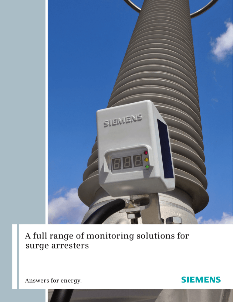
A full range of monitoring solutions for
surge arresters
Answers for energy.
Overview
ACI
ACM basic
ACM advanced
Concept
Electronic
Electronic
Electronic
Measured
variables
3rd harmonic of leakage
current
Number of surge current
impulses
Analyzes surge current impulses
(time stamp, peak value, pulse
width, energy content)
Total leakage current
Total leakage current
3rd harmonic of leakage
current with temperature
correction and harmonic
compensation (3 LEDs)
3rd harmonic of leakage
current with temperature
correction and harmonic
compensation (3 LEDs)
Arrester energy absorption
Power supply
Leakage current
Solar
Solar
Remote indication
No
No
Wireless
Installation
Integrated into ground wire
Integrated into ground wire
Integrated into ground wire
Order no.
3EX5 070
3EX5 080-0
3EX5 080-1
3EX5 085 (USB wireless module)
13
Highly reliable equipment monitoring
with added value
4
ACI
5
ACM basic
6
ACM advanced
8
Surge counters
9
Sensor and display
10
Control spark gap and LCM II
11
Overview
Growth in worldwide energy demand
is putting a greater load on existing
networks – sometimes to the limits of
their capacity – making reliable,
responsible network operation an
increasingly difficult challenge. As a
result, many network operators
are seeking solutions to increase the
dependability of their networks.
Equipment monitoring is a proven
method for recording operating states
and remaining service life, providing
the operator with important data
for asset management. Monitoring
information is also valuable for assessing
the overall state of the network.
2
Efficient monitoring
Surge arresters are highly reliable
components in power transmission and
distribution systems. When operated in
accordance with their specifications, their
service life can span as much as 30 years
without any maintenance.
Nevertheless, overloads may sometimes
occur that can cause arrester failure and
even endanger the safety of the network.
Monitors assist in the early detection of
relevant changes.
Monitors support security of supply on
a whole new level. Siemens offers a
complete line of monitoring devices with
a variety of innovative functionalities
that can be perfectly matched to the
customer’s requirements, ensuring that
impending faults will be detected as early
as possible and before the security of
supply is compromised.
Based on solid experience
Siemens has over 80 years of experience
with surge arresters – a solid foundation
on which to build a comprehensive range
of monitors that are precisely tailored to
today’s surge arrester technology.
Siemens’ line of surge arrester monitors
ranges from simple counters and
condition indicators to periodic analytic
condition monitoring and a future
live condition monitoring system.
All monitors provide the requisite
information on surge arrester responses
and the arrester’s condition – perfectly
matched to the respective voltage level,
network situation, and customer
requirements.
3
ACI – Arrester Condition Indicator
ACI
ACM basic
ACM advanced
Surge counters
Sensor and display
Control spark gap
and LCM II
Overview
Monitors like the arrester condition
indicator (ACI) make safe networks even
safer. Dangerous overvoltages can be
brought under control quickly and safely
by surge arresters, but is it possible to
economically monitor an arrester’s status
simply by keeping an eye on it? It is now!
By observing the indicator, it is possible
to draw conclusions about the operating
state of a connected arrester. The ACI
requires no auxiliary power supply; it
derives its energy from the constant flow
of leakage current.
Always informed
Arrester-specific 3rd harmonic analysis
of leakage current
The ACI shows the arrester’s condition at
a glance, based on an arrester-specific
3rd harmonic analysis of the leakage
current. It works like a traffic light, and is
just as easy to read. The ACI electronically
filters out the 3rd harmonic component
from the arrester’s leakage current.
The arrester’s current condition is
always evident, thanks to the differentcolored LEDs.
Condition “green” means that all values
are within normal range.
Condition “yellow” means that certain
values are deviating, but there is no need
for immediate action. For safety reasons,
the ACI should be checked once a day.
Condition “red” means that there is a risk
of an arrester overload.
4
ACM – Arrester Condition Monitor
Basic version
Even more options compared to an
indicator are possible using arrester
condition monitoring for which Siemens
offers innovative technology with many
new functions.
Basic functions as a solid foundation
The Siemens devices for basic arrester
condition monitoring (ACM) provide
a wide range of standard functions,
including total leakage current
measurement and display, surge current
impulse metering and display, 3rd
harmonic analysis of leakage current
with compensation for networkdependent harmonics, temperature
correction, and condition indication
by means of LEDs in the colors of
traffic lights.
From the first day of operation, the
monitor works in the background to
measure leakage current and compile
a comprehensive counter history.*
Future viability is guaranteed through
the simple option of upgrading to the
advanced system, which requires no
changing of the arrester sensor; it can
even be used as a sensor in future
ISCM (integrated station condition
monitoring) systems.
Thanks to its solar power supply, the
monitor requires no external power
supply or batteries, and no galvanic
connection is established between the
electronics and the arrester’s main
current path. The entire device is encased
in silicone with no hollow spaces, making
it impossible for moisture to penetrate.
* Access only with advanced monitoring
5
ACM – Arrester Condition Monitor
Advanced version
ACI
ACM basic
ACM advanced
Surge counters
Sensor and display
Control spark gap
and LCM II
Overview
The basic functionality of Siemens’ ACM
basic has been expanded to include new
developments and technologies that
improve the safety of energy networks
even more.
The general functions remain the same.
The monitor performs two basic
functions. The first is measuring total
leakage current and determining the
resistive leakage current component
by analyzing the leakage current’s 3rd
harmonic. The second function is
registering surge current impulses,
as well as detecting and registering the
overall number, level, and duration of
impulses. This information can then be
used to perform a precise analysis of
arrester activity.
The ACM advanced solution is
additionally equipped with wireless
communication for evaluating long-term
measurements, counter history, and
energy summation. ACM advanced
offers, and will continue to offer, the
latest in surge arrester monitoring
technology.
6
Automatic long-term trend registration
The ACM advanced automatically
performs a daily leakage current
measurement at a user-defined time and
stores the data obtained for more than
five years. In contrast to simple spot
checks, these long-term measurements
automatically provide optimal
information for trend analysis.
Logging of surge current history and
measurement of energy absorption
In addition to logging a detailed history
of surge current impulses, the ACM
advanced registers unique information
on the energy converted in the surge
arrester per impulse.
This provides a clear and detailed picture
of the surge arrester’s utilization for the
duration of its service life.
Even if the total energy absorption
throughout the arrester’s life cycle has
no limit, this information can still
make a valuable contribution to asset
management.
Solar power supply
Because it is solar powered, the ACM
needs no external power supply or
batteries, nor is there a galvanic
connection between the electronics and
the surge arrester’s main branch circuit.
Ready for IEC 61850
The ACM advanced already meets the
requirements for integration in future
ISCM systems without requiring the
replacement of hardware on the surge
arrester.
PC communication via USB stick
and software
analyze, and evaluate the measured and
calculated data on a PC. It can also be
used to modify and store certain
customer-specific parameters and to
perform software updates, enhancing
both convenience and flexibility.
Easy upgrade
If the basic version is already in use on
a surge arrester, it is possible to upgrade
to the advanced version using a USB
wireless module, free software, and a
specific access license, without having
to modify the arrester. It then has access
to the entire range of functions of this
powerful system.
The USB wireless module (3EX5085) and
the Service Tool can be used to set up a
connection between an ACM and a PC.
The two devices then function as both
transmitter and receiver. The Service Tool
software makes it possible to display,
7
Mechanical counters
ACI
ACM basic
ACM advanced
Surge counters
Sensor and display
Control spark gap
and LCM II
Overview
Surge counters
Technical data for 3EX5030
The 3EX5030 surge counter is a
traditional monitor for surge arresters.
It is integrated into the arrester ground
connection and counts the surge arrester
responses that have occurred.
Response sensitivity:
Surge counter with leakage
current meter
The 3EX5050 surge counter with
leakage current meter also offers
monitoring of arrester leakage current.
In addition to the functions described
here, both surge counters can also be
equipped with a passive auxiliary contact
for remote metering (3EX5030-AC,
3EX5050-AC).
8/20 μs discharge current: 200 A
Resolution: 5 impulses per second
4/10 μs high-current impulse: 100 kA
Technical data for 3EX5050
Response sensitivity:
8/20 μs discharge current: 200 A
Resolution: 5 impulses per second
4/10 μs high-current impulse: 100 kA
Leakage current measurement:
Indicated by mA meter
as peak value / √2
Measuring range up to 30 mA (normal)
or 50 mA (special model: 3EX5050-L)
Bilinear scale
8
Sensor and display
< 200 m
Sensor and display
The 3EX5060 sensor is a surge arrester
monitor that is integrated into the
arrester ground wire. It counts the surge
arrester responses that occur and
continuously measures leakage current.
The 3EX5062 display visualizes the surge
arrester responses detected by the sensor
and the leakage current at a convenient
location. The display can be installed at a
distance of up to 200 meters.
The display unit also provides a
connection for measuring the leakage
current locally – for example, using an
oscilloscope (measuring lead available
as accessory).
Technical data for 3EX5060/062
Response sensitivity:
4/10 μs, 8/20 μs discharge current:
1000 A
30/60 μs discharge current: 200 A
Rectangular-wave discharge current:
100 A
Leakage current measurement:
mA meter measuring range
up to 20 mA
Logarithmic scale
9
Control spark gap and Transinor LCM II
ACI
ACM basic
ACM advanced
Surge counters
Sensor and display
Control spark gap
and LCM II
Overview
Control spark gap
The control spark gap is a monitor for
surge arresters that is integrated into the
arrester’s ground wire. It counts the surge
arrester responses that have occurred
and allows an estimation of the current
flowing through the surge arrester based
on characteristic burn marks.
Live condition monitoring with
Transinor LCM II
The Transinor LCM II is a portable
measuring system for metal-oxide surge
arresters that measures the 3rd harmonic
component of the leakage current
without interrupting operation. The
data obtained can provide valuable
information on the condition of the
arrester.
The specific correction information for
Siemens’ arresters is contained in the
software.
10
Overview
Surge counter
Surge counter with
leakage current indication
Sensor and display
Concept
Electromechanic
Electromechanic
Electromechanic
Measured
variables
Number of surge current
impulses
Number of surge current
impulses
Number of surge current
impulses
Total leakage current
(including DC)
Total leakage current
Power supply
None
None
None
Remote indication
Special model AC:
wired via aux. contact
Special model AC:
wired via aux. contact
Wired
Installation
Integrated into ground wire
Integrated into ground wire
Sensor integrated into
ground wire / display wired
Order no.
3EX5 030
3EX5 030-AC
3EX5 050
3EX5 050-AC
3EX5 050-L
3EX5 060
3EX5 062
11
Control spark gap
LCM II
Spark gap
Electronic
Number of surge current
impulses
Total leakage current
3rd harmonic of leakage
current
None
Battery / mains
Special model:
via optical fiber*
Special model
Integrated into ground wire
Portable / clamp-on ammeter
3EX6 040
3EX6 020*
LCM II
12
Published by and copyright © 2010:
Siemens AG
Energy Sector
Freyeslebenstrasse 1
91058 Erlangen, Germany
Siemens AG
Energy Sector
Power Transmission Division
High Voltage Products
Nonnendammallee 104
13629 Berlin, Germany
For more information, please contact
our Customer Support Center.
Phone: +49 30 386 33 222
Fax:
+49 30 386 26 721
E-mail: arrester@siemens.de
Power Transmission Division
Order No. E50001-G630-A141-X-4A00
Printed in Germany
Dispo 30000, c4bs No. 7457
fb 2390 35/24897 471261 WS 03101.3
Printed on elementary chlorine-free
bleached paper.
All rights reserved.
Trademarks mentioned in this document
are the property of Siemens AG, its affiliates,
or their respective owners.
Subject to change without prior notice.
The information in this document contains
general descriptions of the technical options
available, which may not apply in all cases.
The required technical options should therefore
be specified in the contract.
www.siemens.com/energy


