Document 10582503
advertisement
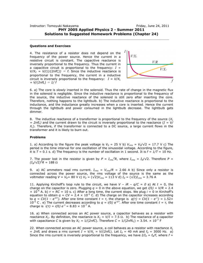
Instructor: Tomoyuki Nakayama Friday, June 24, 2011 PHY 2005 Applied Physics 2 - Summer 2011 Solutions to Suggested Homework Problems (Chapter 24) ________________________________________________________________________________ Questions and Exercises 4. The resistance of a resistor does not depend on the frequency of the power source. Hence the current in a resistive circuit is constant. The capacitive reactance is inversely proportional to the frequency. Thus the current in a capacitive circuit is proportional to the frequency: I = V/XC = V/(1/(2πfC)) ∝ f. Since the inductive reactance is proportional to the frequency, the current in a inductive circuit is inversely proportional to the frequency: I = V/XL = V/(2πfL) ∝ 1/ f 6. a) The core is slowly inserted in the solenoid. Thus the rate of change in the magnetic flux in the solenoid is negligible. Since the inductive reactance is proportional to the frequency of the source, the inductive reactance of the solenoid is still zero after inserting the core. Therefore, nothing happens to the lightbulb. b) The inductive reactance is proportional to the inductance, and the inductance greatly increases when a core is inserted. Hence the current through the lightbulb and power consumed in the lightbulb decrease. The lightbulb gets dimmer. 8. The inductive reactance of a transformer is proportional to the frequency of the source (XL = 2πfL) and the current drawn to the circuit is inversely proportional to the reactance (I = V/ XL). Therefore, if the transformer is connected to a DC source, a large current flows in the transformer and it is likely to burn out. Problems 1. a) According to the figure the peak voltage is V0 = 25 V b) Vrms = V0/√2 = 17.7 V c) The period is the time interval for one oscillation of the sinusoidal voltage. According to the figure, it is T = 0.1 s. d) The frequency is the number of oscillation in 1 second. It is f = 1/T = 10 Hz. 7. The power lost in the resistor is given by P = Irms2R, where Irms = I0/√2. Therefore P = (I0/√2)2R = 188 Ω 9. a) AC ammeters read rms current. Irms = Vrms/R = 2.66 A b) Since only a resistor is connected across the power source, the rms voltage of the source is the same as the voltmeter reading V = VR= 80 V c) V0 = (√2)Vrms = 113 V d) I0 = (√2)Irms = 3.76 A 11. Applying Kirchoff’s loop rule to the circuit, we have V – iR – q/C = 0 a) At t = 0, the charge on the capacitor is zero. Plugging q = 0 in the above equation, we get i(0) = V/R = 2.4 × 10⁻⁶ A. b) τ = RC = 10 s. c) After a long time, the current stops. We plug i = 0 in Kirchoff’s equation to obtain q = CV = 2.4 × 10⁻⁵ C. d) The charge on the capacitor increases according to q = CV(1 – e-t/τ). After one time constant t = τ, the charge is q(τ) = CV(1 – e-1) = 1.52× 10⁻⁵ C . e) The current decreases according to q = i(0) e-t/τ. After one time constant t = τ, the charge is i(τ) = i(0) e-1 = 8.83 × 10⁻⁷ A. 16. a) When connected across an AC power source, a capacitor behaves as a resistor with reactance XC. By definition, the reactance is XC = V/I = 7.5 Ω. b) The reactance of a capacitor with capacitance C is given by XC = 1/(2πfC). Therefore C = 1/(2πfXC) = 3.54. × 10-7 F 22. When connected across an AC power source, a coil behaves as a resistor with reactance XL = 2πfL and draws a rms current I = V/XL = V/(2πfL). Let I0 = 40 mA and f0 = 3000 Hz. a) Since the rms current is inversely proportional to the frequency, we have I/I0 = f0/f, where f = 5 Hz. ⇒ I =I0 = 24 A. b) Now f = 5 MHz. The current is I =I0 = 2.4 × 10⁻⁵ A. 24. a) The rms current in the circuit is I = V/XL = V/(2πfL) = 362 A. b) I = V/XL = V/(2πfL) = 3.62 A c) Since the inductance of a coil is proportional to the permeability of the material in the coil, the inductance of the coil gets 200 times larger when the iron is inserted. L’ = 200L = 3.52 × 10⁻² H. 28. The capacitive reactance and inductive reactance are, respectively, XC = 1/(2πfC) = 79.6 Ω and XL = 2πfL = 785 Ω. Therefore, the impedance of the circuit is Z = √(R2 + (XL – XC)2) = 708 Ω. a) The rms current is I = V/Z = 0.282 A. b) VR = RI = 16.9 V. c) VC = XCI = 22.4 V d) VL = XLI = 221 V. e) VLR = |VL – VC| = 199 V. e) VRC = √(VR2 + Vc2) = 28.1 V. 33. First note that the ohmmeter reading is the resistance R of the wire that makes up the solenoid, not the inductive reactance XL. Since the resonant frequency is given by f0 = 1/(2π√(LC)), the inductance of the solenoid is L = 1/(4π2f02C) = 5.86 × 10⁻⁵ H. To find the voltage, we first calculate the inductive reactance of the solenoid: XL = 2πf0L = 5.41 Ω. At resonance, the inductive reactance and capacitive reactance cancel, thus the impedance of the circuit is Z = R = 2.7 Ω, and the rms current in the circuit is I = V/Z = 6.30 A. The voltage across the solenoid is VLR = √(VR2 + VL2) = I√(R2 + XL2) = 38.1 V. 38. The reactance of the primary coil XL = 2πf0L = 565 Ω, whichis much larger than the resistance of the coil. The impedance of the circuit is Z = √(R2 + XL2) ~ XL = 565 Ω. a) The rms current is I = V/Z = 0.389 A. b) cosφ = R/Z = 0.00133. c) P = IVcosφ = 0.114 W. Note that the power factor and power lost in the coil are both small because of the small resistance compared to the inductive reactance. Thus most of the input power is transferred to the secondary coil 42. a) The voltage of the source is V = √(VR2 + (VL – VC)2) = 33.3 V. b) R = VR/I = 46.7 Ω, XL = VR/I = 83.3 Ω & XC = VC/I = 53.3 Ω c) The impedance of the circuit is Z = V/I = 55.5 Ω. The power factor is cosφ = R/Z = 0.841. 45. The resonant frequency is f0 = 1/(2π√(LC)) = 952 Hz. Thus the circuit is operated at f = f0/2 = 476 Hz. The inductive reactance and capacitive reactance of the components are, respectively: XL = 2πfL = 209 Ω and XC = 1/(2πfC) = 836 Ω. The phase angle is φ = tan-1((XL – XC)/R) = -86.3º. 50. The current changes from 3 A to -3 A in 1/120 second. Therefore, |∆I/∆t| = 720 A/s. By definition, the inductance of the coil is L = ∆VL/|∆I/∆t| = 6.94 H. Since the inductance of a solenoid is given by L = µ0n2Al, the number of turns per unit length is n = √(L/( µ0Al)) = 1.88 × 10⁴ /m. The total number of turns is N = nl = 9.40 × 10³.
