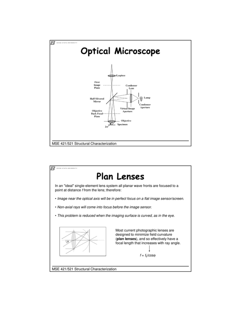
Optical Microscope Plan Lenses
advertisement

Optical Microscope MSE 421/521 Structural Characterization Plan Lenses In an "ideal" single-element lens system all planar wave fronts are focused to a point at distance f from the lens; therefore: • Image near the optical axis will be in perfect focus on a flat image sensor/screen. • Non-axial rays will come into focus before the image sensor. • This problem is reduced when the imaging surface is curved, as in the eye. φ Most current photographic lenses are designed to minimize field curvature (plan lenses), and so effectively have a focal length that increases with ray angle. f = f0/cosφ MSE 421/521 Structural Characterization Achromatic Lenses f (focal length) = f(µ) µblue > µred (dispersion) Chromatic aberration means that a lens will not focus different colors in exactly the same place because the focal length depends on refraction and the index of refraction for blue light (short λ) is larger than that of red light (long λ). The amount of chromatic aberration depends on the dispersion of the glass. MSE 421/521 Structural Characterization Image Formation Three ways to form an image: Projection (shadow) Optical (with lenses) Scanning } all parts of image simultaneously Three requirements for image formation: Brightness Contrast Resolution MSE 421/521 Structural Characterization Electrons vs Light Electron “Optics” Visible Spectrum hν e- 4000 nm ≤ λ ≤ 7000 Å Wavelength of a photon is inversely proportional to its energy, λ = ch/E 100 Å ≤ λ ≤ 2000 Å X-Rays Wavelength of an electron is dependent on its energy (accelerating voltage) Electrons JEOL 2100-HR TEM: λ = 0.0251 Å (200 kV) Hitachi 4500 SEM: λ = 0.0859 Å (20 kV) } 5 orders of magnitude smaller than for visible light! Electrons are much more strongly scattered by matter (EM operates in vacuum) Lenses are magnetic fields (n = 1) rd = Electrons carry a charge 0.61λ α MSE 421/521 Structural Characterization Electrons vs Light Electron “Optics” hν e- Compared to optical microscopy, electron microscopy offers the following advantges: Higher resolution Higher magnification Greater depth of field Crystallographic information Chemical analysis MSE 421/521 Structural Characterization Electron Generation β- The illumination system in an EM consists of a source of electrons (electron gun) and a lens system to focus and control emitted electrons. Electron guns overcome the work function of the electrons by either resistive heating or a strong electric field (or both). Thermionic Emission: A heated wire or crystal is given enough thermal energy to overcome work function (Edison Effect) plus an electric potential (0.5 – 300 kV) to accelerate the electrons. Tungsten (hairpin) W has very high Tm (3422°C) so can have more thermal energy But work function still high (φ = 4.5 eV) even at operating T ≈ 2500°C Cheap ($30) Hitachi S-3400N SEM, LEO 1430 VP SEM LaB6/CeB6 Lower work function (φ = 2.5 eV) than W at operating T ≈ 1500°C, so it is easier to pull electrons off and can have beams 30 times brighter than with W hairpin. Require high vacuum, suffer from thermal shock, and are expensive ($1000). Higher T causes increased volatilisation and premature failure. Tm (LaB6) = 2530°C, Tm (CeB6) = 2540°C. JEOL 2100 HR TEM MSE 421/521 Structural Characterization Electron Generation Field Effect Emission: The field effect gun (FEG) uses a W single crystal and high field (> 109 V/m), which lowers the height of the potential barrier via the Schottky effect. In addition, if the field is sufficiently high, the width of the potential barrier becomes small enough to allow electrons to escape via tunnelling (field emission). Field reduces the work function by ∆φ = 3.8x10⁻⁵F ½ eV Cold FEG operates at room temperature, but requires flashing Thermally-Assisted FEG (Schottky emitter) pointed W crystal (coated with ZrO2) is welded to V-shaped W filament and heated to 1500°C ZrO2 lowers work function (φ = 2.8 eV) improved stability and no flashing enhanced emission by giving some thermal energy, which reduces tunneling distance (really a field-assisted thermionic source) MSE 421/521 Structural Characterization Thermionic Emission Current density at filament surface: j = AT 2e-φ/kT [A/m2] A = 1.20173x10⁶ [A/m2/K2] (Richardson’s constant) T = absolute temperature [K] increases rapidly as T increases & φ decreases (so use high-Tm low-φ material W) Brightness: B = j/(πα2) (j = beam current density, α = convergence semi-angle) (at cross-over: Langmuir equation): B = (jV)/(πkT) [A/m2/sr] V = voltage [V] k = 8.617x10⁻⁵ eV/K Example: For W (φ = 4.5 eV) operating at T = 2500 K and V = 100 kV: j = (1.20173x10⁶ A/m2K2)(2500 K)2exp(-4.5 eV/[(8.617x10-5 eV/K)(2500 K)] = 6364 A/m2 B = (6364 A/m2)(100000 eV)/[(π sr)(8.617x10⁻⁵ eV/K)(2500 K)] = 9.4035x10⁸ A/m2/sr ~9x10⁴ A/cm2/sr MSE 421/521 Structural Characterization Field Effect Emission Current density = j = 6.2x10⁻¹⁰ Temperature-independent -2 (Ef /φ)½F 2 exp-6.8x10⁹φ3/2 Acm Ef + φ F Ef ≈ 5 eV for W at R.T. For a field F > 5x10⁹ V/m, field emission exceeds thermionic emission. To apply such a high field, W has to be prepared as a sharp point of diameter ≈100 nm, which makes it very delicate; therefore, ultra-high vacuum systems (10-8 – 10-9 torr) are necessary – adds cost (JEOL 2100 LaB6 TEM operates at ≈10-7 torr). Low energy spread (δE ≈ 0.3 eV) for improved resolution and better interpretation of EELS data More coherence Highly sensitive to contamination - cold FEG must be flashed every few hours MSE 421/521 Structural Characterization Electron Generation A comparison of electron emission characteristics of W, LaB6, CeB6 and FEG guns W wire LaB6 <100> CeB6 <100> 2500 1500 4.5 2.7 3 Brightness (A cm-2 sr-1) Crossover diameter (mm) Short-term beam current stability (%RMS/hr) <1 <1 <1 3-5 <1 Energy spread at 100 kV (eV) 2 1.5 1.5 0.2 - 0.4 0.5 Typical service life (hr) 30-100 1000 1,500 103 – 104 10,000 Operating vacuum (torr) 10-5 10-7 10-7 10-10 10-9 Evaporation rate (g cm-2s-1) NA 2.2 x 10⁻⁹ 1.6 x 10⁻⁹ NA NA Operating temperature (°C) Work function (eV) Emission current density (A/cm2) Brightness increases linearly with voltage. FEG (cold) FEG (Schottky) 1500 27 1500 ~2.5 4.5 2.8 30 30 17,000 5,300 104 105 105 2x10⁷ 107 30 10 10 0.01 0.02 Resolution determined largely by diameter of beam and δE Thermionic guns have large areas of emission – beam is demagnified x10-4 – very stable and insensitive to contamination Cold FEG has small area of emission – beam is reduced just 5-10x to 1 nm – unstable and very sensitive to contamination, but nearly coherent MSE 421/521 Structural Characterization Triode Electron Gun cathode (heating) (gun bias) Wehnelt kept at slightly more –V (repels electrons) filament kept at large -V >1 mm hole in Wehnelt directly below filament gap between filament and Wehnelt cap is critical to electron focusing and filament lifetime anode and rest of column are earthed The triode produces a beam of electrons which comes to focus (cross-over) just below the Wehnelt cap with a diameter of d0 ≈ 30 µm for W and ≈ 10 µm for LaB6 or CeB6. MSE 421/521 Structural Characterization


