North Fork Clearwater River General Information
advertisement
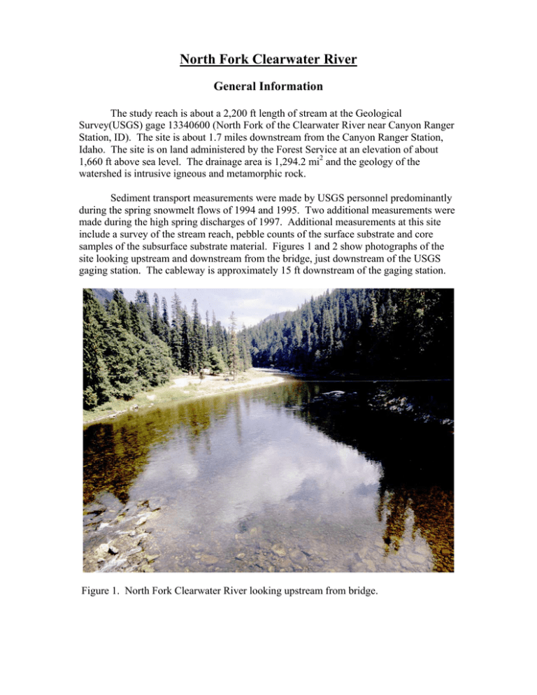
North Fork Clearwater River General Information The study reach is about a 2,200 ft length of stream at the Geological Survey(USGS) gage 13340600 (North Fork of the Clearwater River near Canyon Ranger Station, ID). The site is about 1.7 miles downstream from the Canyon Ranger Station, Idaho. The site is on land administered by the Forest Service at an elevation of about 1,660 ft above sea level. The drainage area is 1,294.2 mi2 and the geology of the watershed is intrusive igneous and metamorphic rock. Sediment transport measurements were made by USGS personnel predominantly during the spring snowmelt flows of 1994 and 1995. Two additional measurements were made during the high spring discharges of 1997. Additional measurements at this site include a survey of the stream reach, pebble counts of the surface substrate and core samples of the subsurface substrate material. Figures 1 and 2 show photographs of the site looking upstream and downstream from the bridge, just downstream of the USGS gaging station. The cableway is approximately 15 ft downstream of the gaging station. Figure 1. North Fork Clearwater River looking upstream from bridge. Figure 2. North Fork Clearwater River looking downstream from the bridge. Streamflow records are available for April 1967 to present. Estimated average annual streamflow (Qa) for the stream is 3,510 ft3/s and the estimated bankfull discharge (Qb) is 16,000 ft3/s. Stream discharge was low in 1994 and the largest daily mean discharge was only 12,600 ft3/s. In 1995 the largest daily mean discharge recorded was 34,200 ft3/s on November 30, well above bankfull discharge. The largest instantaneous discharge for the period of record was 37,500 ft3/s on November 30, 1995. Cross-Section and Channel Geometry Figure 3 shows the cross-section at the sediment transport measurement site, the cableway about 15 ft downstream of the gaging station. The average gradient for that section of the study reach from the downstream bridge and extending about 1000 ft upstream of the gage station is 0.0005 ft/ft. Just upstream of this reach is a steep rapid that was not included in the gradient calculations. 60 North Fork Clearwater River Elevation, ft 50 40 30 20 Qa 10 0 1990 Survey 1998 Survey -10 -20 0 50 100 150 200 250 300 350 400 Distance, ft Figure 3. Cross-section of the North Fork Clearwater River at the USGS cableway. The channel geometry relationships for this cross-section are shown in Figure 4. All data collected in 1994 through 1998 from the cableway were used to develop the displayed power relationships with discharge. Over the range of discharges when sediment transport was measured (3,560 to 34,400 ft3/s) estimated stream width, estimated average depth and estimated average velocity varied from 242 to 295 ft, 5.5 to 100 1000 Top Width 0.087 y = 118.72x 2 R = 0.90 100 10 Average Velocity 0.574 y = 0.025x 2 R = 0.99 1 10 Average Velocity, ft/s Width and Depths, ft North Fork Clearwater River Average Depth 0.339 y = 0.342x 2 R = 0.98 1 100 1000 10000 0.1 100000 3 Discharge, ft /s 11.8 ft, and 2.7 to 9.9 ft/s, respectively. The average reach gradient is 0.0005 ft/ft. Figure 4. Width, average depth, and velocity versus stream discharge at the cableway cross section on the North Fork Clearwater River. (Solid symbols represent data used to develop the power relationship; open symbols were not used because they are either outside the range of discharges when sediment transport was measured or represent data collected prior to 1994.) Channel Material A surface pebble count was made at the cableway cross-section in September 1994. Surface pebble counts were also made along three transects in September 1995 and three cores were collected of subsurface material. The average D50 and D90 for the surface material were 60 mm and 334 mm, respectively, in 1994 and 95 mm and 282 mm, respectively, in 1995. The average D50 and D90 for the subsurface material in 1995 were 23 mm and 135 mm, respectively (Figure 5). The median size of floodplain material was highly variable and the most notable feature is the larger percentage of material smaller than about 0.5 mm. 100 North Fork Clearwater River 90 80 Percent Finer 70 60 50 40 30 Floodplain Samples 20 Surface 1995 Subsurface 1995 Surface 1994 10 0 0.01 0.1 1 10 100 Particle Size, mm Figure 5. Particle size distribution for surface, subsurface and floodplain material samples in the North Fork Clearwater River. 1000 Sediment Transport Sediment transport measurements made in 1994 through 1997 includes 72 measurements of bedload transport and 36 measurements of suspended sediment transport. Sediment transport measurements spanned a range of stream discharges from 3,560 ft3/s (1.01Qa; 0.22Qb) to 34,400 ft3/s (9.80Qa; 2.15Qb). Bedload transport ranged from 0.140 to 5,920 t/d and suspended transport ranged from 21.1 to 411,000 t/d. Over the range of measured discharges, suspended transport accounts for the majority of the material in transport with between one and two orders of magnitude greater suspended transport than bedload transport at all discharges (Figure 6). 1000000 North Fork Clearwater River Sediment Transport, tons/day 100000 10000 1000 100 10 1 Suspended 3.707 y = 7.714E-13x 2 R = 0.92 BCF=1.241 Total Bedload 3.862 y = 4.505E-15x 2 R = 0.88 BCF=1.272 Qa 0.1 1000 Qb Suspended Total Bedload 10000 Discharge, ft3/s Figure 6. Bedload and suspended load transport rate versus discharge. 100000 The bedload transport rates by size class (Figure 7) shows that the larger rates are associated with material in the 0.5 to 2mm diameter size class. Only five of the samples contained particles greater than 32 mm and these were samples with discharges of 14,700 ft3/s and larger. 10000 Bedload Rate, tons/day 1000 100 North Fork Clearwater River <0.5mm 3.576 y = 1.368E-14x 2 R = 0.86 10 0.5-2mm 3.596 y = 2.869E-14x 2 R = 0.85 1 2-8mm 3.937 y = 1.864E-16x 2 R = 0.78 8-32mm 4.181 0.1 y = 2.062E-17x 2 R = 0.81 >32mm 0.01 3.059 y = 3.349E-12x 2 R = 0.55 Qa 0.001 1000 Qb 10000 <0.5mm 0.5-2mm 2-8mm 8-32mm >32mm 100000 3/ Discharge, ft s Figure 7. Bedload transport rate versus discharge for selected size classes. The size of the largest particle in the bedload sample increased with discharge (Figure 8). The largest particle measured in a bedload sample was 74 mm at a discharge of 33,700 ft3/s. At discharges greater than bankfull discharge (16,000 ft3/s) the largest particle exceeded 40 mm in all but one instance. The D50 for most of the bedload samples collected at discharges less than bankfull discharge was in the sand size range, 0.5 to 2 mm. At discharges greater than bankfull discharge the median diameter ranged from 3.6 to 19.9 mm. The largest median diameter of a bedload sample was 19.9 mm for a sample collected at 32,800 ft3/s. The information on the largest particle in the bedload sample and observations of recently moved large rocks and associated instantaneous peak discharges for the 1997 snowmelt period suggest that the median diameter particles on the channel surface begin to move at discharges larger than the bankfull discharge. 1000 North Fork Clearwater River D50 for three surface pebble counts 100 Bedload Size, mm Largest Particle 1997 R2 = 0.64 D50 for three subsurface cores 10 R2 = 0.32 1 Qb Qa 0.1 1000 10000 Median Size Largest Particle 100000 3 Discharge, ft /s Figure 8. Median size of the bedload sample and the largest particle size versus stream discharge for the North Fork Clearwater River.
