et Sprinkler Lateral Design S
advertisement
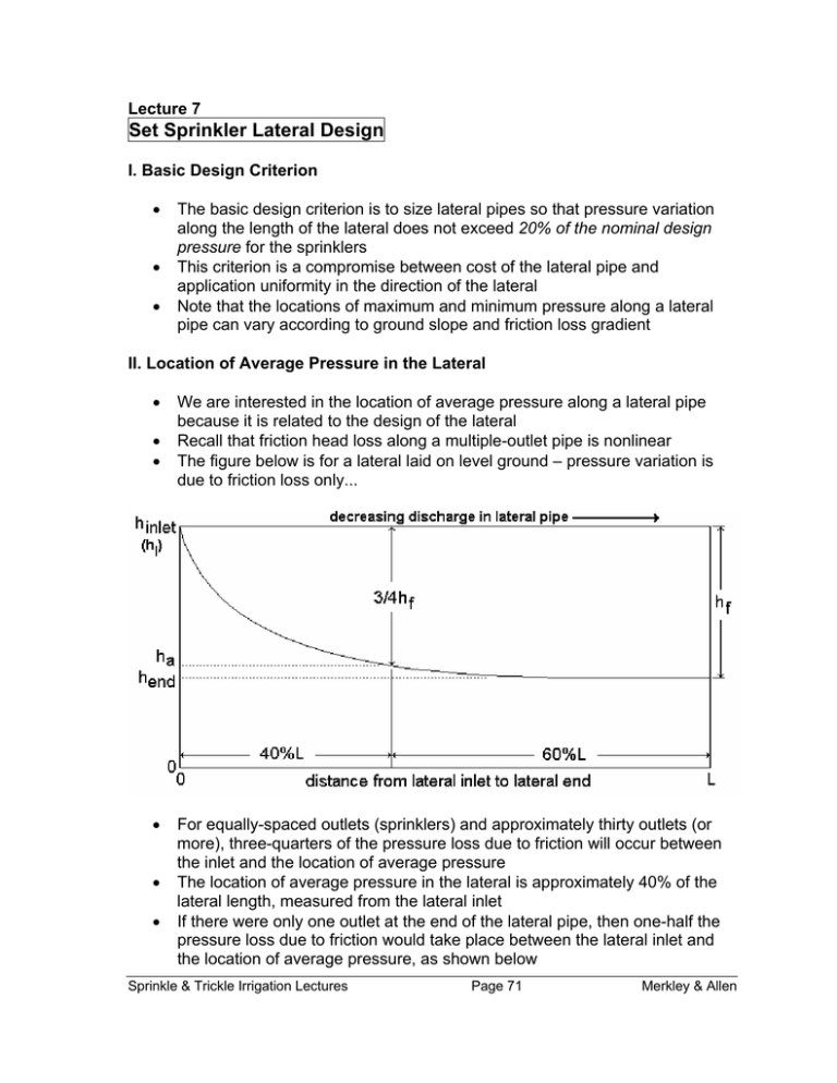
Lecture 7 Set Sprinkler Lateral Design I. Basic Design Criterion • • • The basic design criterion is to size lateral pipes so that pressure variation along the length of the lateral does not exceed 20% of the nominal design pressure for the sprinklers This criterion is a compromise between cost of the lateral pipe and application uniformity in the direction of the lateral Note that the locations of maximum and minimum pressure along a lateral pipe can vary according to ground slope and friction loss gradient II. Location of Average Pressure in the Lateral • • • • • • We are interested in the location of average pressure along a lateral pipe because it is related to the design of the lateral Recall that friction head loss along a multiple-outlet pipe is nonlinear The figure below is for a lateral laid on level ground – pressure variation is due to friction loss only... For equally-spaced outlets (sprinklers) and approximately thirty outlets (or more), three-quarters of the pressure loss due to friction will occur between the inlet and the location of average pressure The location of average pressure in the lateral is approximately 40% of the lateral length, measured from the lateral inlet If there were only one outlet at the end of the lateral pipe, then one-half the pressure loss due to friction would take place between the lateral inlet and the location of average pressure, as shown below Sprinkle & Trickle Irrigation Lectures Page 71 Merkley & Allen • • A computer program can be written to solve for the head loss in the lateral pipe between each sprinkler Consider the following equations: Total friction head loss: (hf )total = ∑i=1(hf )i n (90) Friction head loss to location of ha: ∑i=1∑ j=1(hf ) j = n (hf )a i n +1 (91) where n is the number of sprinklers; (hf)total is the total friction head loss from 0 to L; (hf)i is the friction head loss in the lateral pipe between sprinklers i-1 and i; and (hf)a is the friction loss from the lateral inlet to the location of ha • • • As indicated above, (hf)a occurs over approximately the first 40% of the lateral Note that between sprinklers, the friction head loss gradient is linear in the lateral pipe Note also that (hf)0 = 0, but it is used in calculating (ha)f, so the denominator is (n+1), not n Merkley & Allen Page 72 Sprinkle & Trickle Irrigation Lectures • In applying these equations with sample data, the following result can be found: ( h f )a (hf )total • • • • ≈ 0.73 (92) This supports the above claim that approximately ¾ of the friction head loss occurs between the lateral inlet and the location of ha Also, from these calculations it can be seen that the location of ha is approximately 38% of the lateral length, measured from the inlet, for laterals with approximately 30 or more sprinklers But, this analysis assumes a constant qa, which is not quite correct unless flow control nozzles and or pressure regulators are used at each sprinkler We could eliminate this assumption of constant qa, but it involves the solution of a system of nonlinear equations III. Location of Minimum Pressure in Laterals Running Downhill • The location of minimum pressure in a lateral running downhill is where the slope of the friction loss curve, J, equals the ground slope Sprinkle & Trickle Irrigation Lectures Page 73 Merkley & Allen • • The above assertion is analogous to a pre-calculus “max-min problem”, where you take the derivative of a function and set it equal to zero (zero slope) Here we are doing the same thing, but the slope is not necessarily zero Hazen-Williams Equation: 1.852 12 ⎛ Q ⎞ J = 1.21(10) ⎜ ⎟ ⎝C⎠ D−4.87 (93) for J in meters of friction head loss per 100 m (or ft/100 ft); Q in lps; and D in mm • In this equation we will let: ⎛q ⎞ Q = Ql − ⎜ a ⎟ x ⎝ Se ⎠ • • (94) for multiple, equally-spaced sprinkler outlets spaced at Se (m) from each other, with constant discharge of qa (lps). Ql is the flow rate at the lateral inlet (entrance). To find the location of minimum pressure, let J = S, where S is the ground slope (in %, because J is per 100 m), which is negative for downhill-sloping laterals Combining the two above equations and solving for x, x= ( ) Se ⎡ Ql − 3(10)−7 C ( −S)0.54 D2.63 ⎤ ⎦ qa ⎣ (95) where x is the distance, in m, from the lateral inlet to the minimum pressure Merkley & Allen Page 74 Sprinkle & Trickle Irrigation Lectures • • S is in percent; Se and x are in m; D is in mm; and Ql and qa are in lps Note that the valid range of x is: 0 ≤ x ≤ L, and that you won’t necessarily get J = S over this range of x values: • • • If you get x < 0 then the minimum pressure is at the inlet If you get x > L then the minimum pressure is at the end This means that the above equation for x is valid for all ground slopes: S = 0, S > 0 and S < 0 IV. Required Lateral Inlet Pressure Head • • • Except for the most unusual circumstances (e.g. non-uniform downhill slope that exactly matches the shape of the hf curve), the pressure will vary with distance in a lateral pipe According to Keller & Bliesner’s design criterion, the required inlet pressure head to a sprinkler lateral is that which makes the average pressure in the lateral pipe equal to the required sprinkler pressure head, ha We can force the average pressure to be equal to the desired sprinkler operating pressure by defining the lateral inlet pressure head as: 3 1 hl = ha + hf + ∆he 4 2 • • • (96) hl is the required pressure head at the lateral inlet Strictly speaking, we should take approximately 0.4∆he in the above equation, but we are taking separate averages for the friction loss and elevation gradients – and, this is a design equation Of course, instead of head, h, in the above equation, pressure, P, could be used if desired Sprinkle & Trickle Irrigation Lectures Page 75 Merkley & Allen The value of ∆he is negative for laterals running downhill • For steep downhill slopes, where the minimum pressure would be at the lateral inlet, it is best to let hf = −∆he • • • Thus, we would want to consume, or “burn up”, excess pressure through friction loss by using smaller pipes To achieve this equality for steep downhill slopes, it may be desirable to have more than one pipe diameter in the lateral A downhill slope can be considered “steep” when (approximately)… −∆he > 0.3ha • (97) (98) We now have an equation to calculate lateral inlet pressure based on ha, hf, and he Merkley & Allen Page 76 Sprinkle & Trickle Irrigation Lectures • • However, for large values of hf there will be correspondingly large values of hl Thus, for zero ground slope, to impose a limit on hf we will accept: hf = 0.20ha (for S = 0 only) • • (99) This is the same as saying that we will not allow pipes that are too small, that is, pipes that would produce a large hf value An additional head term must be added to the equation for hl to account for the change in elevation from the lateral pipe to the sprinkler (riser height): 3 1 hl = ha + hf + ∆he + hr 4 2 (100) or, in terms of pressure… 3 1 Pl = Pa + Pf + ∆Pe + Pr 4 2 (101) V. Friction Losses in Pipes with Multiple Outlets • • • Pipes with multiple outlets have decreasing flow rate with distance (in the direction of flow), and this causes the friction loss to decrease by approximately the square of the flow rate (for a constant pipe diameter) Sprinkler and trickle irrigation laterals fall into this hydraulic category Multiply the head loss for a constant discharge pipe by a factor “F” to reduce the total head loss for a lateral pipe with multiple, equally spaced outlets: JFL 100 (102) 1 1 b −1 + + b + 1 2N 6N2 (103) hf = where F is from Eq. 8.9a F= for equally spaced outlets, each with the same discharge, and going all the way to the end of the pipe. • • • All of the flow is assumed to leave through the outlets, with no “excess” spilled out the downstream end of the pipe N is the total number of equally spaced outlets The value of b is the exponent on Q in the friction loss equation Sprinkle & Trickle Irrigation Lectures Page 77 Merkley & Allen • • • • Darcy-Weisbach: Hazen-Williams: b = 2.0 b = 1.852 The first sprinkler is assumed to be located a distance of Se from the lateral inlet Eq. 8.9b (see below) gives F(α), which is the F factor for initial outlet spacings less than or equal to Se F(α) = NF − (1 − α) N − (1 − α) (104) where 0 < α ≤ 1 • • Note that when α = 1, F(α) = F Many sprinkler systems have the first sprinkler at a distance of ½Se from the lateral inlet (α = 0.5), when laterals run in both orthogonal directions from the mainline VI. Lateral Pipe Sizing for a Single Pipe Size • If the minimum pressure is at the end of the lateral, which is the case for no ground slope, uphill, and slight downhill slopes, then the change in pressure head over the length of the lateral is: ∆h = h f + ∆h e (105) If we allow ∆h = 0.20 ha, then 0.20ha = hf + ∆he 0.20ha − ∆he = (106) JaFL 100 (107) and, ⎛ 0.20ha − ∆he ⎞ Ja = 100 ⎜ ⎟ FL ⎝ ⎠ (108) where Ja is the allowable friction loss gradient. • • Lateral pipe diameter can be selected such that J ≤ Ja The above is part of a standard lateral design criteria and will give a system CU of approximately 0.97CU if lateral inlet pressures are the same for each lateral position, for set sprinkler systems Merkley & Allen Page 78 Sprinkle & Trickle Irrigation Lectures • • If the lateral is sloping downhill and the minimum pressure does not occur at the end of the lateral, then we will attempt to consume the elevation gain in friction loss as follows: hf = −∆he (109) ⎛ −∆he ⎞ Ja = 100 ⎜ ⎟ ⎝ FL ⎠ (110) Note that in this case ∆h ≠ hf + ∆he. Rather, ∆h = hmax - hmin, where: 1. hmax is either at the lateral inlet or at the end of the lateral, and 2. hmin is somewhere between the lateral inlet and the end • Given a value of Ja, the inside diameter of the lateral pipe can be calculated from the Hazen-Williams equation: ⎡ K ⎛ Q ⎞1.852 ⎤ D=⎢ ⎜ l⎟ ⎥ ⎢⎣ Ja ⎝ C ⎠ ⎥⎦ 0.205 (111) where Ql is the flow rate at the lateral inlet (Nqa) and K is the units coefficient in the Hazen-Williams equation • The calculated value of D would normally be rounded up to the next available internal pipe diameter VII. Lateral Design Example VI.1. Given information: L= qa = Se = hr = slope = Pa = pipe material = Sprinkle & Trickle Irrigation Lectures 396 m (lateral length) 0.315 lps (nominal sprinkler discharge) 12 m (sprinkler spacing) 1.0 m (riser height) -2.53% (going downhill) 320 kPa (design nozzle pressure) aluminum Page 79 Merkley & Allen VI.2. Calculations leading to allowable pressure head loss in the lateral: Nn = 396/12 = 33 sprinklers F = 0.36 Ql = (0.315)(33) = 10.4 lps ∆he = SL = (-0.0253)(396) = -10.0 m (Pf)a = 0.20Pa - ∆he = 0.20(320 kPa) – 9.81(-10.0 m) = 162 kPa (hf)a = 162/9.81 = 16.5 m VI.3. Calculations leading to required lateral pipe inside diameter: 0.3Pa = 0.3(320 kPa) = 96.0 kPa 0.3ha = 96.0/9.81 = 9.79 m Now, 0.3ha < -∆he (steep downhill). Therefore, may want to use hf = -∆he. Then, Ja is: ⎛ −( −10.0m) ⎞ ⎛ −∆he ⎞ = 100 ⎜ Ja = 100 ⎜ ⎟ ⎟ = 7.01m /100m FL (0. 36)(396) ⎝ ⎠ ⎝ ⎠ (112) However, if 0.3ha > -∆he, Ja would be calculated as: 16.5 ⎛ ⎞ ⎛ 0.20ha − ∆he ) ⎞ Ja = 100 ⎜ = 100 ⎜ ⎟ ⎟ = 11.6m /100m FL (0.36)(396) ⎝ ⎠ ⎝ ⎠ (113) For now, let’s use Ja = 7.01 m/100 m. Then, the minimum pipe inside diameter is (C ≈ 130 for aluminum): ⎡ 1.21E12 ⎛ 10.4 ⎞1.852 ⎤ D=⎢ ⎥ ⎜ ⎟ ⎢⎣ 7.01 ⎝ 130 ⎠ ⎥⎦ 0.205 = 77.7mm (114) which is equal to 3.06 inches. In the USA, 3” aluminum sprinkler pipe has an ID of 2.9” (73.7 mm), so for this design it would be necessary to round up to a 4” nominal pipe size (ID = 3.9”, or 99.1 mm). However, it would be a good idea to also try the 3” size and see how the lateral hydraulics turn out (this is done below; note also that for Ja = 11.6, D = 70.0 mm). Merkley & Allen Page 80 Sprinkle & Trickle Irrigation Lectures VI.4. Check the design with the choices made thus far The real friction loss will be: 1.852 ⎛ 10.4 ⎞ J = 1.21E12 ⎜ ⎟ ⎝ 130 ⎠ hf = ( 99.1 mm)−4.87 = 2.14m /100m JFL (2.14)(0.36)(396) = = 3.06 m 100 100 (115) (116) The required lateral inlet pressure head is: hl = ha + 0.75hf + 0.5∆he + hr hl = 320 / 9.81 + 0.75(3.06) + 0.5( −10.0) + 1.0 = 30.9 m (117) Thus, Pl is (30.9)(9.81) = 303 kPa, which is less than the specified Pa of 320 kPa, and this is because the lateral is running downhill VI.5. Calculate the pressure and head at the end of the lateral pipe hend = hl − hf − ∆he = 30.9 − 3.06 − (−10.0) = 37.8 m (118) which is equal to 371 kPa. Thus, the pressure at the end of the lateral pipe is greater than the pressure at the inlet. To determine the pressure at the last sprinkler head, subtract the riser height to get 37.8 m – 1.0 m = 36.8 m (361 kPa) VI.6. Calculate the location of minimum pressure in the lateral pipe x= ) ( Se ⎡ Ql − 3(10)−7 C( −S)0.54 D2.63 ⎤ ⎦ qa ⎣ ) ( (119) 12 ⎡ x= 10.4 − 3(10)−7 130(2.53)0.54 (99.1)2.63 ⎤ = −39.6 m ⎦ 0.315 ⎣ The result is negative, indicating that that minimum pressure is really at the entrance (inlet) to the lateral pipe. The minimum sprinkler head pressure is equal to hl – hr = 30.9 – 1.0 = 29.9 m, or 293 kPa. Sprinkle & Trickle Irrigation Lectures Page 81 Merkley & Allen VI.7. Calculate the percent pressure variation along the lateral pipe The maximum pressure is at the last sprinkler (end of the lateral), and the minimum pressure is at the first sprinkler (lateral inlet). The percent pressure variation is: ∆P = Pmax − Pmin 361 − 293 = = 0.21% Pa 320 (120) That is, 21% pressure variation at the sprinklers, along the lateral This is larger than the design value of 0.20, or 20% variation. But it is very close to that design value, which is somewhat arbitrary anyway. VI.8. Redo the calculations using a 3” lateral pipe instead of the 4” size In this case, the location of the minimum pressure in the lateral pipe is: x= ) ( 12 ⎡ 10.4 − 3(10)−7 130(2.53)0.54 (73.7)2.63 ⎤ = 196 m ⎦ 0.315 ⎣ (121) which is the distance from the upstream end of the lateral. There are about 196/12 = 16 sprinklers from the lateral inlet to the location of minimum pressure, and about 17 sprinklers from x to the end of the lateral. Friction loss from x to the end of the lateral is: 1.852 Jx −end ⎛ (17)(0.315) ⎞ = 1.21E12 ⎜ ⎟ 130 ⎝ ⎠ (hf )x −end = ( 73.7 )−4.87 = 2.65 m /100 m (122) (2.65)(0.38)(396 − 196) = 2.01 m 100 (123) Friction loss from the inlet to the end is: 1.852 Jinlet −end Merkley & Allen ⎛ 10.4 ⎞ = 1.21E12 ⎜ ⎟ ⎝ 130 ⎠ Page 82 ( 73.7 )−4.87 = 9.05 m /100 m (124) Sprinkle & Trickle Irrigation Lectures (hf )inlet −end = (9.05)(0.36)(396) = 12.9 m 100 (125) Then, friction loss from inlet to x is: (hf )inlet − x = 12.9 − 2.01 = 10.9 m (126) The required lateral pipe inlet head is: hl = ha + 0.75hf + 0.5∆he + hr hl = 320 / 9.81 + 0.75(12.9) + 0.5(−10.0) + 1.0 = 38.3 m (127) giving a Pl of (38.3)(9.81) = 376 kPa, which is higher than Pl for the 4” pipe The minimum pressure head (at distance x = 196 m) is: hx = hl − (hf )inlet − x − ( ∆he )inlet − x (128) hx = 38.3 − 10.9 − (−0.0253)(196) = 32.4 m giving a Px of (32.4)(9.81) = 318 kPa, which is very near Pa. The pressure head at the end of the lateral pipe is: hend = hl − hf − ∆he = 38.3 − 12.9 + 10.0 = 35.4 m (129) giving Pend of (35.4)(9.81) = 347 kPa, which is less than Pl. So, the maximum lateral pipe pressure is at the inlet. The percent variation in pressure at the sprinklers is based on Pmax = 376 -(1.0)(9.81) = 366 kPa, and Pmin = 318 - (1.0)(9.81) = 308 kPa: % ∆P = Pmax − Pmin 366 − 308 = = 0.18 Pa 320 (130) which turns out to be slightly less than the design value of 20% Sprinkle & Trickle Irrigation Lectures Page 83 Merkley & Allen VI.9. What if the lateral ran uphill at 2.53% slope? In this case, the maximum allowable head loss gradient is: ⎛ 0.20ha − ∆he ) ⎞ Ja = 100 ⎜ ⎟ FL ⎝ ⎠ ⎛ 0.2(320 / 9.81) − 10.0 ⎞ = 100 ⎜ ⎟ = −2.44m /100m (0.36)(396) ⎝ ⎠ (131) which is negative because ∆he > 0.2ha, meaning that it is not possible to have only a 20% variation in pressure along the lateral, that is, unless flow control nozzles and or other design changes are made. VI.10. Some observations about this design example Either the 3” or 4” aluminum pipe size could be used for this lateral design. The 4” pipe will cost more than the 3” pipe, but the required lateral inlet pressure is less with the 4” pipe, giving lower pumping costs, assuming pumping is necessary. Note that it was assumed that each sprinkler discharged 0.315 lps, when in reality the discharge depends on the pressure at each sprinkler. To take into account the variations in sprinkler discharge would require an iterative approach to the mathematical solution (use a computer). Most sprinkler laterals are laid on slopes less than 2.5%, in fact, most are on fields with less than 1% slope. Merkley & Allen Page 84 Sprinkle & Trickle Irrigation Lectures
