Intelligent Combustion Controls
For Main and Pilot Burner Fuel Split Optimisation
Answers for Energy
Applicable to Gas Fuel and Dual Fuel DLE versions of the SGT-300 and SGT-400
Small Gas Turbines.
The benefits of lean premixed combustion
systems to reduce NOx emissions are
well demonstrated in industrial gas
turbines. Since the development of the
DLE combustion system, a predefined
fuel schedule was in place to control the
ratio of fuel delivery between the pilot &
main burners across the load range.
Predefined fuel schedules are conservative
and do not take into account any site
specific issues, variations or system
drifts, which can result in warnings/trips
and/or regular onsite tuning activities.
Using predefined fuel schedules also
prevents the engine from running with
optimum NOx emissions. A considerable
amount of time may also be lost during
the Works Acceptance Test (WAT) and
onsite commissioning to find a schedule
that is suitable.
Intelligent combustion control is a control
algorithm that automatically adjusts the
pilot split (within predefined limits) to
reduce high levels of low frequency
(band 1) combustion dynamics and/or
high burner tip temperatures during
normal steady state running.
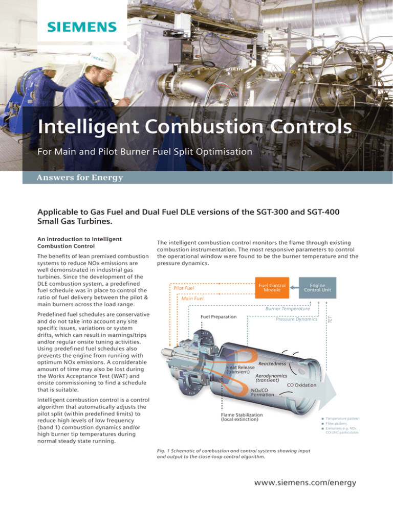
The intelligent combustion control monitors the flame through existing
combustion instrumentation. The most responsive parameters to control
the operational window were found to be the burner temperature and the
pressure dynamics.
Fuel Control
Module
Pilot Fuel
Engine
Control Unit
Main Fuel
Burner Temperature
Fuel Preparation
Pressure Dynamics
Heat Release
(transient)
TET
An introduction to Intelligent
Combustion Control
Reactedness
Aerodynamics
(transient)
CO Oxidation
NOx/CO
Formation
Flame Stabilization
(local extinction)
Temperature pattern
Flow pattern
Emissions e.g. NOx
CO UHC particulates
Fig. 1 Schematic of combustion and control systems showing input
and output to the close-loop control algorithm.
www.siemens.com/energy
Requirement of manual intervention
The split map is set
during commissioning
The engine design is known to
have non-operational regions
that will result in a trip
% Pilot Split
High Burner Tip
Temperatures
High Band 1
Dynamics
Applied Load
Fig. 2 Current Default split schedule
During operation, the engine systems are known to drift (i.e. STAR Fuel Valve) that could result in shifting non-operational regions so that it overlaps the split.
The split map does not always compensate for ambient temperature changes. If it was set for high ambients during
commissioning, then in winter it could result in engine tripping.
Although NOx levels are not
directly controlled or monitored by
the intelligent combustion control,
it is expected that by being able to
run with a leaner pilot split map,
lower levels of NOx emissions can
be achieved with Intelligent
combustion control being able to
compensate for any combustion
dynamics.
Running in close proximity to the
lean blow-out limit in turn results
in the optimum (lowest) NOx,
without affecting CO readings.
The burner temperature is measured by
several thermocouples. The pressure
dynamics are monitored by pressure
transducer(s) and the signal is processed
to provide a measure of the engine’s
susceptibility to the lean blow-out limit.
Inputs for the control algorithm are used
to define operational boundaries
including the Turbine Entry Temperature
(TET) which determine the activation
boundary of the control software.
In this way a predefined schedule line
has been replaced with an operational
field.
The output from the algorithm is the
pilot split, which becomes an
independent parameter, defined solely
on the actual engine readings.
The intelligent combustion control will
help to increase running reliability at
part loads by reducing the number of
trips on high band 1 combustion
dynamics or high tip temperatures.
Why use Intelligent Combustion
Control?
When band 1 dynamics or high tip
temperatures are experienced (the pilot
split is offset from the nominal),
normally there is a physical reason for it:
1. Drift or leakage within the fuel
metering system (i.e. with the STAR
Fuel valve)
2. Burner leaks / blockage
3. Fluctuations of gas fuel composition,
gas pressure and ambient
temperature
Introducing Intelligent Combustion
Control will address some of the
problems (i.e. case 1 or 3), and will
compensate for other issues in the short
term (i.e. case 2).
Solution: Intelligent combustion
control will compensate for:
1. The drift (until the valves are
serviced)
2. Minor variations in the burner flow
area due to leaks or blockage
2
3. Fluctuations in ambient conditions and
fuel composition
% Pilot Split
High Burner Tip
Temperatures
Site
Fluctuations
Site
Fluctuations
High Band 1
Dynamics
Optimum NOx Level
Applied Load
Fig. 3 Intelligent Combustion Control – Default and Re-shaped fuel schedules
Standard Fixed Pre-set % Pilot Split
Where changes in: Fuel CV / Fuel Temperature / Fuel Pressure / Component drift/tolerances (fuel pump) / Specific site
conditions, could lead to either the High Band 1 dynamic limits fluctuating to cause flameout or a failure of the
combustion can(s) due to high tip temperature fluctuation limits.
New Intelligent Combustion Control
Where the % pilot split automatically follows the site fluctuations giving optimum performance limits, flame stabilisation
and increased reliability. As a result, optimum (lowest) NOx levels are achieved.
How does intelligent combustion
control work?
Intelligent combustion control works
by determining an offset to the
nominal split map stored within the
software.
Reduced number of flameouts (can
flame failure) during works
acceptance test, commissioning and
engine operation.
Operating range is divided into a
number of bands with a different
offset for each band allowing for
minimal reshaping of the split map.
Enhanced engine reliability during
transient loads
Offsets are limited based on the
current operating bands.
Applied offset is ramped from the
currently applied offset to the new
required offset upon transitioning
between bands.
Instead of running against a fixed
predefined schedule line, the
optimum split will be identified from
the operational field.
3
Advantages of Intelligent Combustion
Control
Expected reduction in NOx levels
Reduced number of warnings for:
- Burner tip temperatures
- High Band-1 dynamics
Intelligent Combustion Control will
run reliably at the optimum pilot split
for lowest NOx avoiding any other
engine limitations.
Risk is considered to be MINIMAL as
the Active Pilot Software will change
the pilot fuel schedule within
predefined limits and cannot cause
detriment to the engine
performance.
Case Study: SGT-300 in operation at the University of New Hampshire (USA)
WI-1
WI-2
WI-3
% Pilot Split
Previously: Used predefined fuel
schedules, for operation on differing
Wobbe Index (WI) fuels: i.e. Natural
Gas and Processed Landfill Gas. The
graph in Figure 4 presents a number
of the predefined fuel schedules
which would have been required
for operation at different WI.
Predefined
schedules
60%
70%
80%
90%
100%
Normalized TET
Fig. 4 Intelligent Combustion Control – Pre-defined fuel schedules
Predefined fuel schedules were set. This required several maps to cope with the
different fuel compositions
Currently: Reset split fuel
schedule using Intelligent
Combustion Control.
TET act
% Pilot Split
The graph in Figure 5 presents the
field of the fuel schedule available
to the intelligent control algorithm
to operate within. The algorithm
continually responds to the inputs,
changing the pilot split within this
field, to ensure the optimum
operating condition.
WI-1
WI-2
WI-3
Operational
Field
60%
70%
80%
90%
100%
Normalized TET
Fig. 5 Intelligent Combustion Control – Operational Fuel Schedule
Published by and copyright © 2013:
Siemens AG
Energy Sector
Freyeslebenstrasse 1
91058 Erlangen, Germany
Siemens Energy, Inc.
4400 Alafaya Trail
Orlando, FL 32826-2399, USA
For more information, please contact
our Customer Support Center.
Phone: +49 180 524 70 00
Fax:
+49 180 524 24 71
(Charges depending on provider)
E-mail:support.energy@siemens.com
4
www.siemens.com/energy
Energy Service Division
LCN 2013 - F34 LN
Printed on elementary chlorine-free
bleached paper.
All rights reserved. Trademarks mentioned in
this document are the property of Siemens AG,
its affiliates, or their respective owners.
Subject to change without prior notice.
The information in this document contains
general descriptions of the technical options
available, which may not apply in all cases.
The required technical options should
therefore be specified in the contract.


