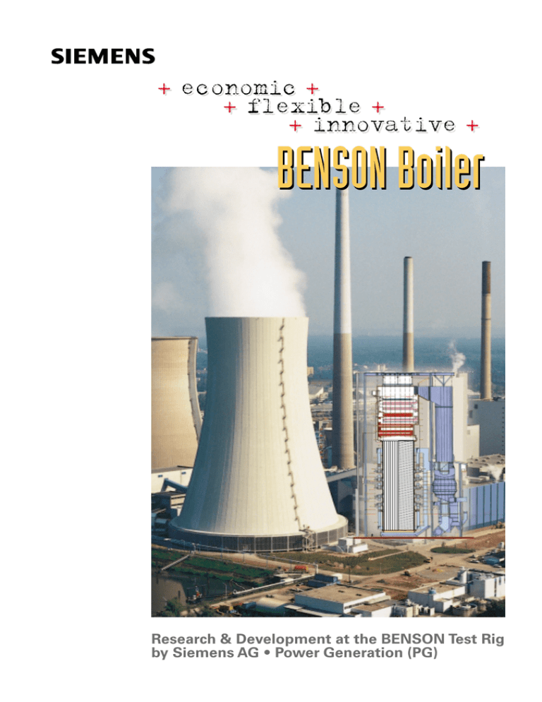
BENSON Boiler + economic + + flexible + + innovative +
advertisement

+ economic + + flexible + + innovative + BENSON Boiler Research & Development at the BENSON Test Rig by Siemens AG • Power Generation (PG) designs and constructs fossil fired power plants manufactures steam and gas turbines, generators, electrical equipment and I&C This booklet should remind you of the exhibition in the monitoring room of the BENSON test rig in Erlangen, Germany, where the fundamental research and development of Siemens/PG is performed on: heat transfer in boiler tubes • smooth vertical, inclined, horizontal • rifled pressure loss in boiler tubes thermoelastic design of water walls feedwater treatment · erosion corrosion is licenser for BENSON boilers develops an improved concept with vertically tubed water walls for BENSON boilers The BENSON know-how allows for reliable design and ensures customer´s benefit via validated codes based on extensive investigations. Siemens AG · Power Generation PG BENSON license BENSON test rig Department PG W7 Freyeslebenstraße 1 D-91058 Erlangen Germany Framatome ANP GmbH (A Framatome and Siemens company) Department FANP NT31 Freyeslebenstraße 1 D-91058 Erlangen Germany Tel: Fax: +49 9131 18-6234 +49 9131 18-6214 email: joachim.franke@erl11.siemens.de Tel: Fax: +49 9131 18-93718 +49 9131 18-92851 email: holger.schmidt@framatome-anp.de 2 Evaporator systems for boilers by Siemens/PG Principle Natural circulation (drum) BENSON with superposed circulation BENSON (once-through) Superheater Evaporator Economizer Operating pressure 10 … 180 bar 20 … 180 bar 20 … 400 bar Water wall tubing vertical vertical spiral or vertical BENSON Boilers are the world-wide most often built once-through boilers with approx. 1000 units: steam pressure up to 310 bar steam temperatures up to 650 °C steam capacities up to 1232 kg/s (4435 t/h) 3 Advantages of BENSON boilers Highest efficiency of power plants Use of worldwide and difficult coals Enthalpy Critical point Modes of operation Pressure (load) Suitable for subcritical and supercritical pressure Wide scope in design (oversized combustion chamber, slag tap furnace) Economical and low-stress operation Flexible operation mode Temperature Load 4-6 %/min 545 °C Load Time Main steam temperature independent of fuel and degree of fouling . Low-stress start-up Rapid load changes with sliding pressure operation Improved concept with vertical tubed water walls based on R&D by Siemens/PG with additional advantages: Simple design and easy maintenance of water walls similar to drum boilers Low part-load of 20% with high steam temperatures Simple start-up system without recirculation pump Optimized flow chracteristic of water wall tubes (see next page) 4 Advantages of BENSON boilers with vertically tubed water walls Once-through characteristic at high mass flux (approx. 1800 kg/m2s) Pressure drop at constant mass flux Friction Due to equal pressure drop in all parallel tubes: System of parallel tubes Hydrostatic Hydrostatic Nominal heated tube Mass flow decreases in the excessively heated tube Excessively heated tube Optimized flow characteristic in case of excessive heat input of water wall tubes due to low mass flux Natural circulation characteristic at low mass flux (approx. 1000 kg/m2s) Pressure drop at constant mass flux Friction Due to equal pressure drop in all parallel tubes: System of parallel tubes Hydrostatic Nominal heated tube Mass flow increases in the excessively heated tube Excessively heated tube 5 Milestones in the field of BENSON boilers 1924 Siemens buys the ”BENSON Patent” from Mark Benson 1926 Siemens manufactures to three BENSON boilers 1929 (30 t/h to 125 t/h) BENSON boilers licence since – state: 2001 1937 Steinmüller 1933 Siemens introduces variablepressure operation 1939 Austrian Energy 1933 Siemens awards licences to several boiler manufacturers 1950 Deutsche Babcock 1949 The world´s first once-through boiler with high steam conditions (175 bar/610 °C) 1954 The first BENSON boiler with supercritical pressure (300 bar/605 °C) 1963 The world´s first spiral-tubed water walls in membrane design 1951 Mitsui Babcock 1954 Babcock & Wilcox 1954 Burmeister & Wain 1954 Kawasaki 1960 Babcock-Hitachi 1987 First hard-coal-fired boiler >900 MW with spiral-tubed water walls 1995 Ansaldo 2000 About 1000 BENSON boilers with >700.000 t/h sold in total 1999 Bharat Heavy Electricals Ltd. (BHEL) 2000 First order of a BENSON boiler with vertical tubed water walls in low mass flux design 6 1996 Foster Wheeler BENSON boiler Boiler activities by Siemens/PG Boiler concepts Arrangement of heating surfaces Thermal hydraulic design New water wall/evaporator design • Vertical tubed water walls with optimized rifled tubes • BENSON Boiler with superposed circulation • Horizontal evaporator tubes for advanced power plants with fluidized bed combustion or coal gasification Start-up systems Increase of availability Control concepts Water chemistry Interaction of boiler and turbine R&D Computer programs • Reliable design based on extensive knowledge of heat transfer and flow stability • Material preservation by thermal elastic component design • Prevention of pipe wall thinning and resulting failures Reduction of operating cost • Low pressure loss and steady-state flow condition in evaporator zones and separators • Optimized feedwater chemistry 7 BENSON test rig and range of parameters investigated Test section Spray condenser Pressurizer Main heater Preheater Dosing pump Technical data: System pressure Temperature Mass flow Heat capacity Trickle cooler Circulation pump Feedwater tank Piston pump 330 600 28 2000 bar °C kg/s kW Main cooler Reduction valve Tube Geometry Number of measurements > 100.000 > 160.000 Heating uniform one-side uniform one-side vertical Tube orientation inclined horizontal Test parameter Pressure Mass flux Test matrix for heat tansfer and pressure drop investigations 8 25 ≤ p ≤ 280 bar 100 ≤ m ≤ 2500 kg/m2 s Heat flux 0 ≤ q ≤ 950 kW/m2 Tube inner diameter 8≤d ≤ 50 mm Heat transfer and pressure drop in boiler tubes Schematic course of wall temperature and pressure loss in an uniformly heated vertical smooth evaporator tube Heat transfer region Steam Convective heat transfer to steam flow Steam quality 1.0 Post -CHF region/ Post-dryout region Boiling crisis 0.8 ∆p ∆L 0.6 Wall temperature Convective heat transfer through water film Fluid temperature 0.4 0.2 Saturated nucleate boiling 0 Subcooled boiling Convective heat transfer to water flow Pressure loss gradient Temperature Water 9 Heat transfer in boiler tubes Effect of gravity on heat transfer in inclined and horizontal smooth tubes Inner wall temperature (°C) 600 Inclined tube Calculation with WATHUN 500 Pressure 50 Mass flux 1000 Heat flux 400 Tube inner diameter 24.3 400 bar kg/m2s kW/m2 mm 300 200 0.40 0.45 0.50 Steam quality 0.55 0.60 15° Inner wall temperature (°C) 600 Horizontal tube Pressure 100 bar Mass flux 500 kg/m2s Heat flux 300 kW/m2 Tube inner diameter 24.3 mm 500 400 300 Fluid 200 0 0.2 0.4 0.6 Steam quality 10 0.8 1.0 Heat transfer in boiler tubes Improvement in heat transfer by rifled tubes Wall temperature in smooth and rifled tubes Pressure Mass flux Heat flux 150 bar 500 kg/m2s 300 kW/m2 Steam quality Fluid 1.0 Rifled tube 0.8 Smooth tube 0.6 0.4 10 0 Rifled tube 20 0 30 0 40 0 50 0 60 0 Inner wall temperature (°C) Smooth tube 11 Heat transfer in boiler tubes Wall temperatures in vertical rifled tubes at different loads Inner wall temperature (°C) High load Pressure Mass flux Peak heat flux 212 bar 770 kg/m2s 310 kW/m2 400 Calculation with WATHUN 375 Fluid 350 Pressure Mass flux Peak heat flux Low load 325 Fluid 300 1600 1800 2000 2200 2400 2600 2800 Fluid enthalpy (kJ/kg) 12 100 bar 250 kg/m2s 200 kW/m2 Heat transfer in boiler tubes Optimized rifled tubes reduce wall temperatures or allow mass flux reduction Inner wall temperature (°C) Smooth tube Mass flux 1000 kg/m2s 440 Standard rifled tube Mass flux 1000 kg/m2s 420 400 Optimized rifled tube Mass flux 1000kg/m2s 380 360 Calculation with Pressure WATHUN 212 bar Peak heat flux 310 kW/m2 440 Standard rifled tube Mass flux 1000 kg/m2s Optimized rifled tube Mass flux 770 kg/m2s 420 400 380 Smooth tube Mass flux 1500 kg/m2s 360 1800 2000 2200 2400 Fluid enthalpy (kJ/kg) 13 Pressure loss in smooth and rifled boiler tubes Pressure Mass flux Heat flux Tube inner diameter Related pressure loss 100 bar 1000 kg/m2s 100 kW/m2 ca.13 mm Location of boiling crisis 20 ∆p wet steam ∆p water 16 12 Calculation with DRUBEN Rifled tube 8 4 Smooth tube Wetted surface Unwetted surface 0 0 0.2 0.4 0.6 0.8 1 Steam quality Smooth tube Water 14 Rifled tube Steam Thermoelastic design of water walls increases flexibility (1) Rack plate ϑ1 σ1 177 ϑ2 σ2 176,5 13,8 178 9,37 181 183 4,91 182 0,45 184 -4,01 186 188 190 192 8,47 8,44 12,9 191 194 4,01 -8,47 193 4,01 Temperature field ϑ [°C] Stress field σ [N/mm2] Measured values Temperature and stress fields in a rack plate at a gradient of 10 K/min, quasi-steady-state conditions 15 Thermoelastic design of water walls increases flexibility (2) Firing 500 °C Stress analysis with WATHAN based on R&D increases reliability of water walls 380 °C WATHAN Input data: pressure, temperature, mass flux, steam quality, heat flux, geometry WATHUN-calculation (heat transfer coefficients) Stress analysis Fatigue analysis (for p/pk < 1) FEM-calculation Temperature field Thermal stress Mechanical stress FEM-calculation Temperature field Thermal stress differences (Wetted and unwetted tube) Stress assessment Primary stress < Sm ∑ Primary and secondary stress < 3 Sm Service life assessment Thermal stress Permissible differences range of stress Height [m] σax,T+P 60 qmax 50 . q Position σax,W TF TW σal σef Nomenclature . q Average heat flux . qmax Max. loc. heat flux Fluid temperature TF TW Wall temperature 40 30 σef σax,T+P σ1,T+P σ2,T+P σax,W σal 20 10 σ2,T+P σ1,T+P 0 100 300 Heat flux [kW/m2] 16 400 500 Temperature [°C] 0 400 500 Stress [N/mm2] Effective stress Axial stress (T+P) Princ. stress1 (T+P) Princ. stress2 (T+P) Axial stress (weight) Allowable stress Feedwater treatment . Erosion-corrosion (1) Appearance Parameters of influence Material (Cr-, Mo-, Cu-contents) Geometry (pipe, bend, etc.) Fluid velocity Temperature Steam quality Feedwater chemistry (pH, O2) Exposure time Mechanism Fe3 O4 Fe OH+ Oxide layer (magnetite) protects against erosion-corrosion Metal loss caused by erosion-corrosion (mass transfer) Fe (OH)2 Velocity profile Steel Wall adjacent turbulent layer Flow core 17 Feedwater treatment . Erosion-corrosion (2) Effect of material composition pH = 9,5; O2 = < 5ppb pH = 7; O2 = < 5 ppb pH = 7; O2 = 500ppb Wall thinning mm/a 10 St 37.2 5 15 Mo3 2 1 Ferritic steel 15 NiCuMoNb 5 5 13 CrMo 4 4 2 10 CrMo 9 10 0.1 X10CrNiTi 18 9 Austenitic steel 5 St 37.2+5µm-Metco 33-coating 2 0.01 5 2 0.001 18 T = 180 v = 20 t = 200 °C m/s h Feedwater treatment . Erosion-corrosion (3) Effect of thermal hydraulic and water chemistry parameters Measurement v = 35 m/s pH = 7 O2 ≤ 5 ppb t = 200 h Carbon steel Measurement T = 180 °C pH = 7 O2 ≤ 5 ppb t = 200 h Carbon steel Measurement T = 120 °C v = 35 m/s pH ≤ 5 ppb t = 200 h Carbon steel Measurement T = 180 °C v = 39 m/s O2 ≤ 5 ppb t = 200-400h Carbon steel Wall thinning mm/a 10 5 2 1 5 2 0,1 5 2 0,01 5 Calculation with WATHEC 2 0,001 0 20 40 Fluid velocity (m/s) 0 100 200 Water temperature (°C) 6 8 10 pH 0 200 400 Oxygen concentration (ppb) 19 Research & development by Siemens/PG allows reliable design of BENSON boilers based on computer programs as: WATHUN Heat transfer DRUBEN Pressure drop STADE Flow distribution in parallel tube systems DEFA/DEFOS Design of boilers DYNASTAB Dynamic stability WATHAN Material strength WATHEC/COMSY Erosion-corrosion Printed by and copyright (2001): Siemens Power Generation Freyeslebenstaße 1 D-91058 Erlangen Germany Siemens Aktiengesellschaft Subject to change without prior notice


