Determination of the Electric Field inside a Microwave Resonator
advertisement
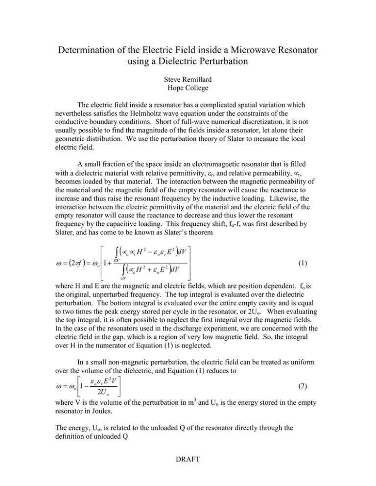
Determination of the Electric Field inside a Microwave Resonator using a Dielectric Perturbation Steve Remillard Hope College The electric field inside a resonator has a complicated spatial variation which nevertheless satisfies the Helmholtz wave equation under the constraints of the conductive boundary conditions. Short of full-wave numerical discretization, it is not usually possible to find the magnitude of the fields inside a resonator, let alone their geometric distribution. We use the perturbation theory of Slater to measure the local electric field. A small fraction of the space inside an electromagnetic resonator that is filled with a dielectric material with relative permittivity, εr, and relative permeability, µr, becomes loaded by that material. The interaction between the magnetic permeability of the material and the magnetic field of the empty resonator will cause the reactance to increase and thus raise the resonant frequency by the inductive loading. Likewise, the interaction between the electric permittivity of the material and the electric field of the empty resonator will cause the reactance to decrease and thus lower the resonant frequency by the capacitive loading. This frequency shift, fo-f, was first described by Slater, and has come to be known as Slater’s theorem ( ) µ o µ r H 2 − ε o ε r E 2 dV ∫ (1) ω = (2πf ) = ω o 1 + ∆V 2 2 µ o H + ε o E dV ∫ ∆V where H and E are the magnetic and electric fields, which are position dependent. fo is the original, unperturbed frequency. The top integral is evaluated over the dielectric perturbation. The bottom integral is evaluated over the entire empty cavity and is equal to two times the peak energy stored per cycle in the resonator, or 2Uo. When evaluating the top integral, it is often possible to neglect the first integral over the magnetic fields. In the case of the resonators used in the discharge experiment, we are concerned with the electric field in the gap, which is a region of very low magnetic field. So, the integral over H in the numerator of Equation (1) is neglected. ( ) In a small non-magnetic perturbation, the electric field can be treated as uniform over the volume of the dielectric, and Equation (1) reduces to ε o ε r E 2V ω = ω o 1 − (2) 2U o where V is the volume of the perturbation in m3 and Uo is the energy stored in the empty resonator in Joules. The energy, Uo, is related to the unloaded Q of the resonator directly through the definition of unloaded Q DRAFT S. Remillard, Perturbation Measurement of Electric Field Q= ωU o (3) Pd where Pd is the microwave power dissipated inside the resonator. The dissipated power is proportional to, but not equal to, the available power, Pav, coming out of the power amplifier by Q Q 4 L 1 − L Q Q Pd = Pav ⋅ (4) β2 1+ β1 where QL is the measured, or loaded, Q of the resonator, β1 is the input coupling coefficient, and β2 is the output coupling coefficient. To determine the electric field inside from measured values of f, fo, β1 and β2, Equation 2 is solved for Uo and substituted into Equation 3. Equation 4 is also substituted into Equation 3 and the whole mess is solved for E in Volts/meter Q Q 4 L 1 − L Q Q Q 1 E = Pav ⋅ ( f o − f ) ⋅ 2 πf o ε r ε oV β 1+ 2 β1 = P ⋅ ( f − f )⋅ A av o (5) where, for lack of any other name, the factor A will be called the “dissipation coefficient”. Q, QL, β1 and β2 are measured on the empty cavity. It should be remembered that this is for electric perturbations in negligible magnetic field only. To determine the local electric field at a point inside a cavity resonator, place a dielectric of known permittivity, such as Teflon with εr=2.1, at the point of interest. The only measurement needed with the dielectric is resonant frequency, f. With the dielectric removed, measure the resonant frequency, fo, along with Q, QL, β1 and β2. Use Equation 5 to calculate the quantity A ⋅ ( f o − f ) . The electric field is then known for all levels of the available power through E= Pav A ⋅ ( f o − f ) , where Pav is in Watts. DRAFT
