Microcooler Array with Elemental In‐Plane Flow
advertisement
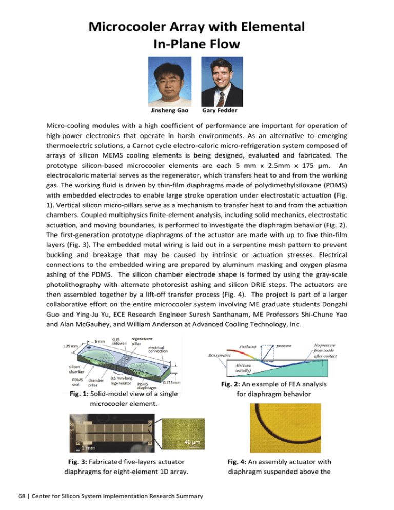
Microcooler Array with Elemental In‐Plane Flow Jinsheng Gao Gary Fedder Micro‐cooling modules with a high coefficient of performance are important for operation of high‐power electronics that operate in harsh environments. As an alternative to emerging thermoelectric solutions, a Carnot cycle electro‐caloric micro‐refrigeration system composed of arrays of silicon MEMS cooling elements is being designed, evaluated and fabricated. The prototype silicon‐based microcooler elements are each 5 mm x 2.5mm x 175 μm. An electrocaloric material serves as the regenerator, which transfers heat to and from the working gas. The working fluid is driven by thin‐film diaphragms made of polydimethylsiloxane (PDMS) with embedded electrodes to enable large stroke operation under electrostatic actuation (Fig. 1). Vertical silicon micro‐pillars serve as a mechanism to transfer heat to and from the actuation chambers. Coupled multiphysics finite‐element analysis, including solid mechanics, electrostatic actuation, and moving boundaries, is performed to investigate the diaphragm behavior (Fig. 2). The first‐generation prototype diaphragms of the actuator are made with up to five thin‐film layers (Fig. 3). The embedded metal wiring is laid out in a serpentine mesh pattern to prevent buckling and breakage that may be caused by intrinsic or actuation stresses. Electrical connections to the embedded wiring are prepared by aluminum masking and oxygen plasma ashing of the PDMS. The silicon chamber electrode shape is formed by using the gray‐scale photolithography with alternate photoresist ashing and silicon DRIE steps. The actuators are then assembled together by a lift‐off transfer process (Fig. 4). The project is part of a larger collaborative effort on the entire microcooler system involving ME graduate students Dongzhi Guo and Ying‐Ju Yu, ECE Research Engineer Suresh Santhanam, ME Professors Shi‐Chune Yao and Alan McGauhey, and William Anderson at Advanced Cooling Technology, Inc. Fig. 1: Solid‐model view of a single microcooler element. Fig. 3: Fabricated five‐layers actuator diaphragms for eight‐element 1D array. Fig. 2: An example of FEA analysis for diaphragm behavior Fig. 4: An assembly actuator with diaphragm suspended above the 68 | Center for Silicon System Implementation Research Summary


