Ballistics Project, (partial) Example Report 1 Overview Name Here
advertisement
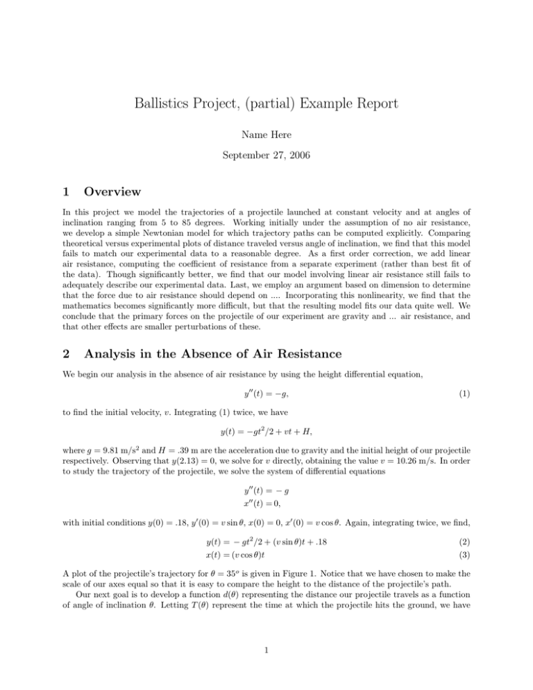
Ballistics Project, (partial) Example Report Name Here September 27, 2006 1 Overview In this project we model the trajectories of a projectile launched at constant velocity and at angles of inclination ranging from 5 to 85 degrees. Working initially under the assumption of no air resistance, we develop a simple Newtonian model for which trajectory paths can be computed explicitly. Comparing theoretical versus experimental plots of distance traveled versus angle of inclination, we find that this model fails to match our experimental data to a reasonable degree. As a first order correction, we add linear air resistance, computing the coefficient of resistance from a separate experiment (rather than best fit of the data). Though significantly better, we find that our model involving linear air resistance still fails to adequately describe our experimental data. Last, we employ an argument based on dimension to determine that the force due to air resistance should depend on .... Incorporating this nonlinearity, we find that the mathematics becomes significantly more difficult, but that the resulting model fits our data quite well. We conclude that the primary forces on the projectile of our experiment are gravity and ... air resistance, and that other effects are smaller perturbations of these. 2 Analysis in the Absence of Air Resistance We begin our analysis in the absence of air resistance by using the height differential equation, y ′′ (t) = −g, (1) to find the initial velocity, v. Integrating (1) twice, we have y(t) = −gt2 /2 + vt + H, where g = 9.81 m/s2 and H = .39 m are the acceleration due to gravity and the initial height of our projectile respectively. Observing that y(2.13) = 0, we solve for v directly, obtaining the value v = 10.26 m/s. In order to study the trajectory of the projectile, we solve the system of differential equations y ′′ (t) = − g x′′ (t) = 0, with initial conditions y(0) = .18, y ′ (0) = v sin θ, x(0) = 0, x′ (0) = v cos θ. Again, integrating twice, we find, y(t) = − gt2 /2 + (v sin θ)t + .18 x(t) = (v cos θ)t (2) (3) A plot of the projectile’s trajectory for θ = 35o is given in Figure 1. Notice that we have chosen to make the scale of our axes equal so that it is easy to compare the height to the distance of the projectile’s path. Our next goal is to develop a function d(θ) representing the distance our projectile travels as a function of angle of inclination θ. Letting T (θ) represent the time at which the projectile hits the ground, we have 1 Projectile Trajectory at 35 Degrees 5 Height 4 3 2 1 35 degrees 0 0 1 2 3 4 5 6 7 8 9 10 11 Horizontal distance Figure 1: Trajectory for no air resistance at 35 Degrees. y(T (θ)) = 0, which for y(t) as in equation (2) can readily be solved with the quadratic formula. Once T (θ) is established, we compute from equation (3) q v sin θ + v 2 sin2 θ + 2(.18)g . d(θ) = v cos θ · T (θ) = v cos θ g For angles θ ∈ [5, 85], d(θ) is plotted along with our experimental data in Figure 2. We observe that the predicted distance is too small for small angles and postulate that the initial velocity for this model is too small. The discrepancy between curves in the region θ ∈ [30, 60] indicates that air resistance must play a critical role for this object. Distance Vs Angle of Inclination 12 Experimental data No air resistance 11 10 Distance in Meters 9 8 7 6 5 4 3 2 0 10 20 30 40 50 60 Angle of Inclination in Degrees 70 80 90 Figure 2: Distance traveled versus angle of inclination Last, by setting d′ (θ) = 0, we find that the angle that maximizes distance traveled in the absence of air resistance is θmax = 44.52o. A MATLAB diary sesssion for this last calculation is included below. The first angle is greater than 90o and we discard it. 2 >>dprime=diff(’10.26*cos(theta)*(10.26*sin(theta)+sqrt(10.26ˆ2*sin(theta)ˆ2 + 2*9.81*.18))/9.81’,’theta’); >>solve(dprime) ans = [ 2.3644436914239447535064124780192] [ .77714896216584848495623090526033] 3 Analysis for Linear Air Resistance You’re on your own now. 3
