Radiation Protection Dosimetry Advance Access published December 21, 2006
Radiation Protection Dosimetry (2006), 1 of 5
doi:10.1093/rpd/ncl454
TESTING THE STAND-ALONE MICROBEAM AT
COLUMBIA UNIVERSITY
G. Garty, G. J. Ross, A. W. Bigelow, G. Randers-Pehrson and D. J. Brenner
Columbia University, Radiological Research Accelerator Facility, 136 S. Broadway,
Irvington, NY 10533, USA
The stand-alone microbeam at Columbia University presents a novel approach to biological microbeam irradiation studies.
Foregoing a conventional accelerator as a source of energetic ions, a small, high-specific-activity, alpha emitter is used. Alpha
particles emitted from this source are focused using a compound magnetic lens consisting of 24 permanent magnets arranged
in two quadrupole triplets. Using a ‘home made’ 6.5 mCi polonium source, a 1 alpha particle s–1, 10 lm diameter microbeam
can, in principle, be realised. As the alpha source energy is constant, once the microbeam has been set up, no further
adjustments are necessary apart from a periodic replacement of the source. The use of permanent magnets eliminates the need
for bulky power supplies and cooling systems required by other types of ion lenses and greatly simplifies operation. It also
makes the microbeam simple and cheap enough to be realised in any large lab. The Microbeam design as well as first tests of
its performance, using an accelerator-based beam are presented here.
INTRODUCTION AND OVERALL DESIGN
Columbia University’s Radiological Research Accelerator Facility (RARAF) currently offers its users
access to a few-micron diameter single-cell/singleparticle (proton/Helium) microbeam irradiator,
based on a recently installed 6 MV Singletron particle accelerator and an electrostatic quadrupole triplet. In order to further reduce the beam diameter
and increase the range of radiation fields available,
intensive development work is being performed on
a new, six-element lens(1) for focusing the microbeam
down to submicron sizes, on a heavy ion source(2)
for generating higher LET beams and on a proton
induced soft X ray microbeam(3). During this development work we foresee long periods where the
electrostatic particle microbeam will be unavailable
for biology. In order to continue providing this
essential service to our users during the down time,
a second microbeam irradiator, which can be operated either directly from the accelerator or using an
isotopic source, is being developed.
The ‘so-called’ stand alone microbeam (SAM)
consists of a 210Po source, focused by a compound
magnetic lens on to the end-station of the decommissioned collimated microbeam beamline at RARAF.
Simulations indicate that, using a 6.5 mCi 210Po
source, a beam flux of 1 particle s 1 onto a 10 mm
diam. spot is achievable with this geometry(4,5).
Alternatively, a higher beam flux and potentially
smaller spot size is achievable when the source is
removed and beam from the accelerator is let into
Corresponding author: gyg2101@columbia.edu
the lenses. In addition to providing a secondary
user facility at RARAF, the design is simple and
inexpensive enough that the SAM can be reproduced
in any large radiation biology laboratory.
SAM LAYOUT
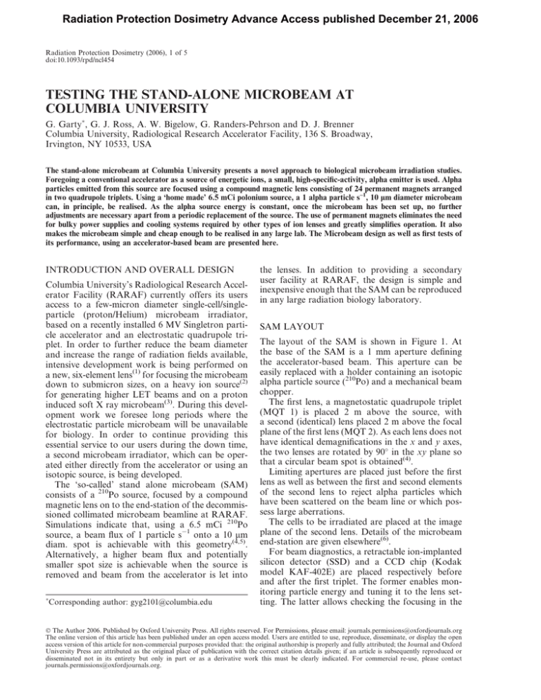
The layout of the SAM is shown in Figure 1. At
the base of the SAM is a 1 mm aperture defining
the accelerator-based beam. This aperture can be
easily replaced with a holder containing an isotopic
alpha particle source (210Po) and a mechanical beam
chopper.
The first lens, a magnetostatic quadrupole triplet
(MQT 1) is placed 2 m above the source, with
a second (identical) lens placed 2 m above the focal
plane of the first lens (MQT 2). As each lens does not
have identical demagnifications in the x and y axes,
the two lenses are rotated by 90 in the xy plane so
that a circular beam spot is obtained(4).
Limiting apertures are placed just before the first
lens as well as between the first and second elements
of the second lens to reject alpha particles which
have been scattered on the beam line or which possess large aberrations.
The cells to be irradiated are placed at the image
plane of the second lens. Details of the microbeam
end-station are given elsewhere(6).
For beam diagnostics, a retractable ion-implanted
silicon detector (SSD) and a CCD chip (Kodak
model KAF-402E) are placed respectively before
and after the first triplet. The former enables monitoring particle energy and tuning it to the lens setting. The latter allows checking the focusing in the
Ó The Author 2006. Published by Oxford University Press. All rights reserved. For Permissions, please email: journals.permissions@oxfordjournals.org
The online version of this article has been published under an open access model. Users are entitled to use, reproduce, disseminate, or display the open
access version of this article for non-commercial purposes provided that: the original authorship is properly and fully attributed; the Journal and Oxford
University Press are attributed as the original place of publication with the correct citation details given; if an article is subsequently reproduced or
disseminated not in its entirety but only in part or as a derivative work this must be clearly indicated. For commercial re-use, please contact
journals.permissions@oxfordjournals.org.
G. GARTY ET AL.
equipment while also significantly simplifying SAM
operation. In addition, simulations have shown that
the spherical aberrations in a magnetic triplet are
about three times lower than in an equivalent
electrostatic quadrupole triplet(1,5).
Prior to ordering the lens as well as during its
tuning, extensive use has been made of both finite
element analysis and analytical calculations(8) to
characterise the spot size dependence on pole tip
strength, misalignment of the lenses and residual
higher order fields (hexapole and octapole). The lens
itself consists of two quadrupole-triplets; each
triplet consisting of two 4.25 mm long magnetostatic
quadrupoles, surrounding an 8.5 mm long quadrupole, rotated at 90 to the other two. The two triplets
are also rotated 90 to each other giving Russian
symmetry. Each quadrupole strength can be tuned
by extending or retracting four NdFeB magnets
inside a shaped yoke, using micrometric screws(9).
TUNING THE MAGNETS
Figure 1. (a) A scheme and (b) photo of the SAM. See text
for details. The two lines in a) are theoretical predictions of
the beam profile in the x and y directions.
first triplet. The final beam size is measured at the
image plane using the knife edge technique(7)
The SAM superstructure was designed to provide
mechanical rigidity and fix the relative positions of
the source, magnets and biological endstation. The
SAM is rigidly connected to an optical table and
coupled to the accelerator using a floppy bellows.
Any mechanical vibrations will pivot the SAM as
one unit around the biological endstation rather
than distorting it. The stability of the SAM to thermal fluctuations still needs to be studied systematically although no significant fluctuations were seen
on a day to day basis.
ION OPTICS
The compound magnetic lens used in the SAM is
based on the electrostatic quadrupole sextuplet
designed for the electrostatic microbeam(1). In
order to simplify the SAM operation, and making
use of the fact that this is a fixed-energy beam that
requires no daily tuning, the lens was constructed
using permanent magnets. The lack of large coils in
the design allows for a smaller pole-face gap for the
magnet, resulting in better focusing properties. The
use of permanent magnets also eliminates the
need for costly power supplies and bulky cooling
The RARAF accelerator was used to generate a
1 mm collimated beam, mimicking the alpha particles generated by an isotopic source. The accelerator
beam was scattered on a 2 mm thick aluminium foil
to obtain a large solid angle spread coming into the
lens resulting in a 100 particle s 1 beam at the image
plane. Using this foil the energy spectrum of the beam
matches that of the required 210Po source (as verified
using a solid state detector). This beam was used to
tune the lenses, in two stages. At first a commercial
CCD chip was placed at the expected focal plane of
the first triplet. Alpha particles impinging on the
CCD chip deposit electrons directly in the CCD
well, resulting in a light spot in the obtained image.
However, the well depth in the CCD chip used was
not sufficiently deep and as a result typically 4–9
pixels were illuminated by each alpha particle.
Furthermore, at high rates (hundreds of particles
s 1) ghosting, i.e. false light spots generated by
alpha particles hitting the CCD shift register during
the readout phase, was apparent. Both problems
were overcome by tuning the beam to a low rate
and locating, in each frame, the centre of gravity of
each light spot. The resulting 2-D histogram is
shown in Figure 2.
After the first lens was tuned to its optimal focusing, the CCD was removed. The second lens was
brought to the same settings and the beam spot at
the image plane was optimised. During this optimisation Russian symmetry of the lenses(1) was maintained. In particular quadrupoles 1, 3, 4 and 6 were
kept at the same setting (A) and quadrupoles 2 and
5 at the same setting (B).The beam spot size was
measured using the knife edge technique(7), namely,
a thin foil was scanned across the beam and the
fraction of degraded particles reaching a solid state
2 of 5
TESTING THE STAND-ALONE MICROBEAM AT COLUMBIA UNIVERSITY
Figure 2. Beam profile at the waist of the beam just above
the first magnetic quadrupole triplet, as measured on the
CCD. The white elipse represents the theoretical prediction
of 50 150 mm . The tilt is due to rotation of the CCD with
respect to the quadrupoles.
detector was measured as a function of the foil
edge position. Figure 3a shows an example of the
integrated beam profile obtained with this method.
Numerically, the FWHM of the beam is obtained as
the reciprocal slope at the transition region.
Figure 3 also shows theoretical and measured spot
shapes at various settings in AB space. The theoretical values (Figure 3b) were obtained by a fifth order
matrix calculation using GIOS2000(8) and reach an
optimal beam spot of 10 mm diam. Experimentally,
a 20 mm spot was reproducibly obtained, as demonstrated in Figure 3a and c. During the magnet tuning
elliptical spots, with either axis (but not both) 10 mm
long, were measured. This implies that a 10 mm round
beam is attainable. The apparent discrepancy between the obtained spot size and the theoretically
predicted one is probably due to residual high
order moments (mostly octapoles) which were not
yet completely eliminated from the lenses. GIOS
calculations show that 1% octapole moment in the
quadrupoles may double the spot size. In addition
the spot size was seen to be extremely sensitive to the
alignment of the lenses with respect to each other. It
is possible that this alignment is not yet good enough.
HIGH SPECIFIC-ACTIVITY ISOTOPIC
RADIATION SOURCE
When operated in an offline mode, a radioactive
source is placed instead of the SAM entrance
aperture. The radioactive source must be a monochromatic alpha emitter with a half-life short enough
Figure 3. (a) Raw data from the knife edge scan of the
optimal beam. The open and closed symbols represent two
orthogonal scans of the same beam. (b) Theoretical and (c)
measured aspect ratio and relative size of the beam at the
image plane of the SAM. The axes of (c) are in turns of the
micrometric screw with each turn representing a 5% change
in magnetic field.
to provide sufficiently high specific activity, yet long
enough to allow a few months of operation between
source replacements. 210Po is ideal for this purpose,
as it has a half-life of 138 d and decays via a single
channel (a 5.305 MeV alpha particle) into a stable
daughter (206Pb). The specific activity of pure 210Po
is 4.5 103 Ci g 1 (1.7 1014 DPS g 1).
The source diameter should be made as small as
possible, to minimise spot size for given demagnification,
and its thickness should be made as large as possible,
to obtain sufficiently high activity. On the other
hand, in order to limit the chromatic aberrations,
due to the varying degradation of alpha particles
3 of 5
G. GARTY ET AL.
Figure 4. A photo of the plating setup. See text for details.
created within the source, the source must be extremely thin. Based on SRIM(10) as well as beam optics
simulations, the optimal thickness of the source is
200 nm, yielding an energy spread of 40 keV and an
activity of 6.5 mCi (2.4 108 DPS)(5). Assuming the
alpha particles are emitted to 4p, beam optics simulations predict a beam flux of just over 1 alpha
particle s 1 at the focal plane, which is sufficient
for many applications of a single-particle
microbeam. At this source thickness the spherical
and chromatic aberrations are about the same(5).
As such a source is not commercially available, a
setup for electroplating 210Po on the tip of
a platinum wire was designed and assembled
(Figure 4). As an anode, a 1.5 ml Fabmate (graphite)
crucible is used. It is loaded with 1 ml of polonium
solution (Isotope Product Laboratories , CA) containing the required activity. Approximately 2 V are
placed between the platinum wire and the crucible,
using a voltage regulated power supply. The plating
set-up is placed on an orbital mixer (Thermolyne
RotoMix) as mixing the solution assists in
preventing depletion of the polonium from the vicinity of the cathode. The plating processes is done in
a vented glove box with an active charcoal filter, as
210
Po may become volatile and is extremely toxic. So
far several small sources (0.1–100 mCi) have been
made. The rate of plating was seen to be proportional to the concentration of polonium in solution.
This means that the time required to plate a certain
fraction of the polonium present in the solution is
independent of the actual amount plated. It is therefore expected that a source of any size can be made
within 24 h of plating. A 6.5 mCi source has not yet
been produced, as our radioactive source license
amendment is pending.
CONCLUSIONS
A microbeam irradiator based on a compound magnetostatic lens was designed and built at Columbia
University’s RARAF. The focusing properties agree
well with those predicted by GIOS 2000. As seen from
these calculations the lens is extremely sensitive to its
self alignment as well as to high order moments resulting in a factor of 2 degradation of spot size over the
theoretically predicted one. These problems will be
overcome shortly with better alignment of the magnets and finer tuning of their strength and symmetry.
So far the SAM has only been tested with an
accelerator-based beam although it has been
designed around operation with a custom made
6.5 mCi 210Po alpha emitter. Such a source is
currently under development.
Once fully optimised the SAM will provide a useful secondary microbeam facility at RARAF and
will enable biology to be performed in parallel with
developments on the electrostatic microbeam. Based
on our experience, a similar facility can be reproduced in any large radiobiology lab, although the
tuning and alignment procedures are faster when an
accelerator is available.
ACKNOWLEDGEMENTS
This work was partially supported by the Department of Energy (DOE-grant #DE-FG0201ER63226) and by the national institute of biomedical imaging and Bioengineering (NIBIB-grant
#8P41EB002033). The authors would also like to
thank Dr Barney Doyle for his suggestion of using
the CCD chip for beam imaging. Open access for
this paper provided by the National Institute of
Allergy and Infectious Diseases (NIAID-grant
#U19A1067773).
REFERENCES
1. Dymnikov, A. D., Brenner, D. J., Johnson G. W. and
Randers-Pehrson, G. Theoretical study of short electrostatic lens for the Columbia ion microprobe. Rev. Sci.
Instr. 71, 1646–1650 (2000).
2. Bigelow, A. W., Randers-Pehrson, G. and
Brenner, D. J. Laser ion source development for the
Columbia University microbeam. Rev. Sci. Instr. 73,
770–772 (2002).
3. Schettino, G., Randers-Pehrson, G. and Brenner D. J.
Development of a soft X-ray microbeam at RARAF,
Proceedings of the 4th international workshop:
microbeam probes of cellular radiation response. Rad.
Res. 166, 661–662 (2006).
4. Ross, G. J., Garty, G., Randers-Pehrson, G. and
Brenner, D. J. A single-particle/single-cell microbeam
based on an isotopic alpha source. Nucl. Instr. Meth.
B 231, 207–211 (2005).
5. Garty,
G.,
Ross,
G.
J.,
Bigelow,
A.,
Randers-Pehrson, G. and Brenner, D. J. A microbeam
irradiator without an accelerator. Nucl. Instr. Meth. B
241, 392–396 (2005).
6. Randers-Pehrson, G., Geard, C., Johnson, G.,
Elliston, C. D. and Brenner, D. J. The Columbia
University single-ion microbeam. Rad. Res. 156,
210–214 (2001).
4 of 5
TESTING THE STAND-ALONE MICROBEAM AT COLUMBIA UNIVERSITY
7. Bigelow, A. W., Ross, G. J, Randers-Pehrson, G.
and Brenner, D. J. The Columbia University
Microbeam II endstation for cell imaging and
irradiation. Nucl. Instr. Meth. B 231, 202–206
(2005).
8. Wollnik, H.,
Brezina, J.
and Berz, M.
Gios-beamtrace—a program package to determine
optical-properties of intense ion-beams. Nucl. Instr.
Meth. A 258, 408–411 (1987).
9. Gottschalk, S. C., Dowell, D. H. and Quimby, D. C.
Permanent magnet systems for free-electron lasers.
Nucl. Instr. Meth. A 507, 181–185 (2003).
10. Ziegler, J. F. and Manoyan, J. M., Nucl. Instr. Meth.
B 35, 215–228 (1988).
5 of 5


