Journal of Magnetism and Magnetic Materials 155 (1996) 151 - 153
a•
Journal of
magnetism
and
magnetic
, i ~ materials
ELSEVIER
Quantum magnetic disk
Stephen Y. Chou *, Peter R. Krauss
NanoStructure Laboratory. Department of Electrical Engineering. Unil,ersity o["Minnesota Minneapolis. MN 55455, USA
Abstract
A quantum magnetic disk (QMD) - a new paradigm for magnetic recording - is proposed and fabricated. Tile QMD
consists of pre-fabricated single-domain magnetic structures that have an identical shape and are uniformly embedded in a
nonmagnetic disk. Each single-domain structure has a quantized magnetic moment and can store one bit of information. The
QMD has a number of advantages over the conventional disk and is suitable for ultra-high density recording. Two processes
based on electron beam nanolithography and other nanofabrication technologies have been developed to fabricate QMDs.
QMDs with a density of 65 Gbits/in 2 - over two orders of magnitude greater than the state-of-the-art magnetic storage
density - have been demonstrated. A method for mass production of QMD without employing lithography is discussed.
1. Introduction
In a conventional magnetic disk (CMD), a writing head
must simultaneously define the location, shape, and magnetization moment of each bit. A slight error in doing so
could lead to errors in reading the bit and neighboring bits.
The bits on CMDs are stored in a continuous thin magnetic
film. Often, there are no recognizable boundaries between
bits, making their reading and writing 'blind' and dependent solely upon the mechanical accuracy of the drive. The
continuous film also can exhibit cross-talking in high
density storage, namely the switching of one bit will
automatically switch a neighboring bit due to the exchange
lbrce.
Naturally, one could ask whether it would not be better
if the writing head did not need to define the location,
shape and magnetization moment of each bit? Wouldn't it
be better if the disk drive could see each bit before reading
and writing it? Wouldn't it be better if the exchange force
between the bits and hence the cross-talk could be reduced? The quantum magnetic disk (QMD) - a new
paradigm for ultrahigh density magnetic disk that we
proposed here - is a major step in this direction [1].
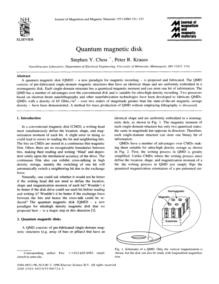
identical shape and are uniformly embedded in a nonmagnetic disk, as shown in Fig. I. The magnetic moment of
each single-domain structure has only two quantized states:
the same in magnitude but opposite in direction. Therefore,
each single-domain structure can store one binary bit of
information.
QMDs have a number of advantages over CMDs making them suitable for ultra-high density storage as shown
in Fig. 2. First, the writing process in QMD is greatly
simplified. Unlike CMDs where the writing process must
define the location, shape, and magnetization moment of a
bit, the writing process in QMD just simply flips the
quantized magnetization orientation of a pre-patterned sin-
./'~Nonmagnetic~
/
2. Quantum magnetic disks
A QMD consists of pre-fabricated single-domain magnetic structures (e.g. array of bars or pillars) that have an
Corresponding
chou@ee.umn.edu.
author:
Fax:
+ 1-612-625-4583;
email:
Fig. I. Schematic of a QMD. Only the vertical magnetization is
shown, but the disk can also be made with longitudinal magnetization.
0304-8853/96/$15.00 © 1996 Elsevier Science B.V. All rights reserved
SSDI 0 3 0 4 - 8 8 5 3 ( 9 5 ) 0 0 7 2 4 - 5
152
S.Y. Chou, P.R. Krauss / Journal of Magnetism and Magnetic Materials 155 (1996) 151-153
(~onventional
Quantum
\
V
IVl
• Many bits are connected
• Each bit is separated from others
by nonmagnetic materials.
=> Can NOT track each bit
individually
=> Can track each bit individually
Fig. 2. Comparison of writing, reading, and tracking of bits in CMDs and QMDs.
gle-domain magnetic structure. This means that in a QMD,
even when the writing head partially overlaps with neighboring bits, it is still possible to write perfectly just the
intended bit without altering the neighboring bits as long
as the writing head overlaps with the intended bit most.
This also implies that a perfect writing in QMD can be
achieved with a writing head of a size that is much smaller
or larger than the size of a bit. In other words, in QMD,
the precise definition of the bits is done only once during
disk fabrication with relatively low cost due to mass
production. As a result, the requirements for the writing
process which constantly occurs during disk usage can be
relaxed.
Second, QMD can track every bit individually but
CMD cannot. This is because in a QMD, each bit is
separated from the other bits by nonmagnetic material, but
in CMD many bits are connected. The individual-bit-tracking ability allows precise positioning and lower error rate.
Third, reading in QMD should have much less jitter
than that in CMD. The reason is that in CMDs, the
boundary between bits is ragged due to grain size; in
QMD, each bit can have edges much smoother than the
grain size and is well separated from other bits.
Fourth, the non-magnetic materials which separate the
bits in a QMD cut off the exchange interactions between
the neighboring bits, thus greatly reducing the crosstalk
problem.
And fifth, by controlling the size and shape anisotropy
of each bit as well as the interface between the bit and
nonmagnetic material, one can achieve unique coercivity
and switching processes in the single-domain magnetic
structures which may be impossible in thin film storage
media.
3. Fabrication
Two fabrication methods have been developed for
ricating QMDs with perpendicular magnetic moment.
first method results in ultrahigh density arrays of
standing nanoscale single-domain nickel structures [2].
fabThe
free
The
Fig. 3. SEM image of 3 by 3 bits of a QMD with 65 Gbits/in -~
density. Each bit consists of a nickel pillar uniformly embedded in
200 nm SiO2 with a 50 nm diameter (aspect ratio of 4) and a
period of 100 nm.
153
S. K Chou, P.R. Krauss / Journal of Magnetism and Magnetic Materials 155 (1996) 151 153
0.5 nm
150
...~
I
200 "-~.~
250
(a)
, /
! //
"~/N
(b)
Fig. 4. TMAFM image (a) and MFM image (b) of 3 by 3 bits of a QMD with 65 Gbits/in-" density. The TMAFM image shows a very
smooth surface and the MFM image shows an alternating pattern of bit magnetization directions.
fabrication process begins with a silicon substrate onto
which a thin plating base and PMMA film were deposited.
First, a high resolution electron beam lithography system
was used to expose dot arrays in the PMMA. The exposed
PMMA was removed in a development process. Second,
an electroplating process was used to selectively deposit
nickel into the PMMA template openings. Third, the
PMMA was removed leaving free standing nickel pillars.
The second QMD fabrication method results in ultrahigh density arrays of nanoscale single-domain nickel
structures embedded in a SiO 2 film with an extremely
smooth top surface [3]. The fabrication begins by depositing on a silicon substrate a thin plating base, SiO 2 film,
chrome film, and PMMA film. First, electron beam lithography was used to expose dot arrays in the PMMA. After
developing, the dot arrays were transferred into the chrome
film. Second, reactive ion etching was used to etch the
array of holes down to the plating base beneath. Third, an
electroplating process was used to selectively deposit nickel
into the SiO 2 template openings. Fourth, chemical mechanical polishing was used to remove overplated nickel giving
a surface with a RMS roughness of 0.5 nm.
4. Characteristics
A QMD of 65 Gbits/in 2 density fabricated using the
second process has been investigated using SEM (Fig. 3),
tapping mode atomic force microscopy (TMAFM) (Fig.
4a), and magnetic force microscopy (MFM) (Fig. 4b). The
TMAFM image shows a very smooth surface with a RMS
roughness of 0.5 rim. The MFM image corresponding to
the same area clearly shows the 3 by 3 bit array has an
alternating magnetization pattern. One orientation of mag-
netization is indicated by bright spots, and the other orientation by dark spots. For these measurements the QMD
was first demagnetized. The magnetization orientation of
individual bits can be switched using the localized magnetic field from an MFM tip thereby writing data on the
QMD.
5. Fabrication without nanolithography
To mass produce QMD cost-effectively, a process without using lithography must be developed. One of the
candidate processes is to make a mold that contains an
array of uniform pillars [4]. The mold will create uniform
vias in a nonmagnetic layer on top of disks by molding.
Then magnetic materials will be deposited in the vias by
CVD, electroless plating, or other methods. Finally, chemical mechanical polishing will be used to achieve a smooth
finished surface.
Acknowledgements
It gives us great pleasure to thank Lingshu Kong for
MFM measurements and Robert Guibord for his technical
assistance in fabrication. This work was partially supported
by ONR, ARPA and a Packard Fellowship. The MFM is
supported by ARO through a DURIP.
References
[1] S.Y. Chou, M. Wei, P.R. Krauss, and P.B. Fischer, J. Vac.
Sci. Technol. B 12 (1994) 3695.
[2] P.R. Krauss, P.B. Fischer. and S.Y. Chou, J. Vac. Sci. Technol. B 12 (1994) 3639.
[3] P.R. Krauss and S.Y. Chore J. Vac. Sci. Technol. B 13 (1995)
2850.
[4] S.Y. Chou. Private communication. August 1994.


