Lecture 21
Lecture 21
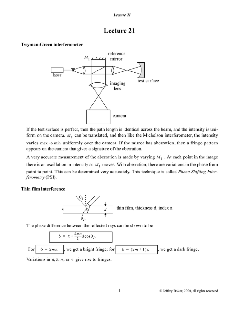
Twyman-Green interferometer
reference
mirror
M1
laser
imaging
lens
test surface
camera
If the test surface is perfect, then the path length is identical across the beam, and the intensity is uniform on the camera. M 1 can be translated, and then like the Michelson interferometer, the intensity
varies max min uniformly over the camera. If the mirror has aberration, then a fringe pattern
appears on the camera that gives a signature of the aberration.
A very accurate measurement of the aberration is made by varying M 1 . At each point in the image
there is an oscillation in intensity as M 1 moves. With aberration, there are variations in the phase from
point to point. This can be determined very accurately. This technique is called Phase-Shifting Interferometry (PSI).
Thin film interference
1
n
d
thin film, thickness d, index n
P
The phase difference between the reflected rays can be shown to be
4n
= + ---------- d cos P
For
= 2m
= 2m + 1
, we get a bright fringe; for
, we get a dark fringe.
Variations in d n , or give rise to fringes.
1
© Jeffrey Bokor, 2000, all rights reserved
Lecture 21
Newton rings
screen
BS
flat reference plate
If the test surface is spherical, concentric ring fringes are observed. The reference surface must be
well-known.
– Useful for testing flats. Quick test on spheres.
– Reference surface could also be spherical.
Anti-reflection (AR) coating
I0
I0
I1
n0
I1
air
d
n
ng
I2
film
glass
The Fresnel reflection coefficient at the top surface is
n – n 0
R o = ---------------
n + n 0
2
Io = Ro Io
where the typical value for R o is ~ 4%.
At the bottom surface:
2
n g – n
R g = ---------------
n g + n
I1 Io Rg
I 1 and I o interfere destructively if
4nd
= ------------- = 2m + 1
m = 0 1 2
3 5
or nd = 2m + 1 --- = --- ------ ------
4
4 4
4
“quarter wave”
The net reflected intensity is zero if I 1 and I o are equal, but out of phase.
2
© Jeffrey Bokor, 2000, all rights reserved
Lecture 21
ng – n
n–n
--------------o- = -------------n + no
ng + n
So,
n – no ng + n = ng – n n + no
n 2 – n o n g – n o n + nn g = n g n – n 2 – nn o + n o n g
2n 2 = 2n o n g
n =
no ng
GUIDED WAVE OPTICS
[Reading Assignment, Hecht 5.6]
Optical fibers
The step index circular waveguide is the most common fiber design for optical communications
n1
n2
plastic coating
(sheath)
core
cladding
For guiding to occur, we will see that the necessary condition is that
n2 n1
.
For communications, optical fibers offer extraordinary advantages over either free-space radio, or
coaxial cable as a transmission medium:
1.low loss
2.no crosstalk between fibers
3.no electromagnetic interference
4.small, light, flexible
5.huge bandwidth
For analysis simplicity – we consider an infinite slab waveguide. This allows us to perform a simpler
2D analysis in Cartesian coordinates. However, this planar waveguide configuration is not just aca-
3
© Jeffrey Bokor, 2000, all rights reserved
Lecture 21
demic - this is the structure used in double-heterostructure laser diodes and other integrated optical
devices.
Consider 2D analysis
(infinite in y-direction)
x
x=a
y
x = a
n1
z
n2
n1
We first consider a ray optics analysis:
n 1 cladding
1
2
n 2 core
By Snell’s law
n 2 cos 2 = n 1 cos 1
n2
cos 1 = ----- cos 2
n1
Note: not our usual definition of the angles
Note the use of the grazing angle (angle with respect to the surface) instead of the incidence angle
(angle with respect to the normal). This leads to the cosine instead of the sine form of Snell’s law.
If n 2 n 1 , then at the critical angle c
n2
----- cos c = 1
n1
1 = 0
.
For 2 c , there is no refracted ray due to total internal reflection.
The ray then reaches opposite interface at same 2 , and is reflected again:
For 2 c , there is never a transmitted ray at the interface, so there is no loss.
4
© Jeffrey Bokor, 2000, all rights reserved
Lecture 21
But for 2 c , light leaks out to the cladding, and there is rapid attenuation along z .
This shows us that the input rays should be at a small angle to be guided.
What about refraction at the input face?
2
0
n0 = 1
sin 0 = n 2 sin 2
Snell’s law at the input face:
For guiding to occur, we then see that there is the following condition on the input angle:
sin 0 n 2 sin c
n 2 1 – cos c2 1 / 2
sin 0 n 22 – n 12 1 / 2
For optical fiber, we also use the concept of numerical aperture, NA = sin max . So the NA of the
fiber is given simply by:
Example: n 2 = 1.5
NA =
NA = n 22 – n 12 1 / 2
.
n 1 = 1.4
1.5 2 – 1.4 2 = 0.54
max = 32
The usefulness of this definition is that we can see how large the lens NA should be to efficiently couple light into the fiber.
5
© Jeffrey Bokor, 2000, all rights reserved


