Experiment 2 Diffraction and Interference
advertisement
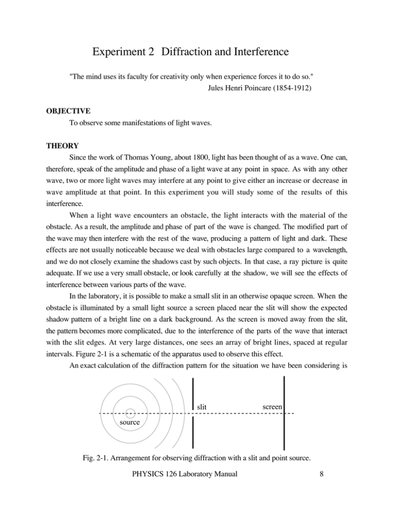
Experiment 2 Diffraction and Interference "The mind uses its faculty for creativity only when experience forces it to do so." Jules Henri Poincare (1854-1912) OBJECTIVE To observe some manifestations of light waves. THEORY Since the work of Thomas Young, about 1800, light has been thought of as a wave. One can, therefore, speak of the amplitude and phase of a light wave at any point in space. As with any other wave, two or more light waves may interfere at any point to give either an increase or decrease in wave amplitude at that point. In this experiment you will study some of the results of this interference. When a light wave encounters an obstacle, the light interacts with the material of the obstacle. As a result, the amplitude and phase of part of the wave is changed. The modified part of the wave may then interfere with the rest of the wave, producing a pattern of light and dark. These effects are not usually noticeable because we deal with obstacles large compared to a wavelength, and we do not closely examine the shadows cast by such objects. In that case, a ray picture is quite adequate. If we use a very small obstacle, or look carefully at the shadow, we will see the effects of interference between various parts of the wave. In the laboratory, it is possible to make a small slit in an otherwise opaque screen. When the obstacle is illuminated by a small light source a screen placed near the slit will show the expected shadow pattern of a bright line on a dark background. As the screen is moved away from the slit, the pattern becomes more complicated, due to the interference of the parts of the wave that interact with the slit edges. At very large distances, one sees an array of bright lines, spaced at regular intervals. Figure 2-1 is a schematic of the apparatus used to observe this effect. An exact calculation of the diffraction pattern for the situation we have been considering is slit screen source Fig. 2-1. Arrangement for observing diffraction with a slit and point source. PHYSICS 126 Laboratory Manual 8 very difficult. Fortunately, there is a simpler case, which is sketched in Fig. 2-2. The crucial differences are that the slit is illuminated with plane waves, and that our observations are made at distances large compared to the slit width. A simple geometric argument, given in your text, yields the angular position of the minima (dark regions) in the diffraction pattern. For a slit of width a, illuminated with light of wavelength , the result is asin = m m = ±1, ±2, ±3K (2-1) This tells us that the minima are evenly spaced when is small, and that we can find a from , or vice versa. The complete pattern is shown in Fig. 2-3. The same arrangement of an incident plane wave and a distant screen leads to a more interesting pattern for an obstacle consisting of two identical slits separated by a distance d. Each slit will produce its own diffraction pattern. When the slits are close together, the patterns will overlap, so only one is apparent. In addition the wavefront coming from one slit will interfere with the wavefront coming from the other. The resulting pattern of light and dark bands is superimposed on the single slit diffraction pattern. Another geometric argument gives the angular position of the dark bands as d sin = (m + 12 ) m = 0, ±1,±2K (2-2) Again, the complete intensity pattern is shown in Fig. 2-3. EXPERIMENTAL PROCEDURE Our light source is a small laser, used here because it is a convenient way to obtain intense monochromatic plane waves. The diffraction objects are a slit formed by sharp metal edges and several photographic slides with various groups of transparent slits. D a slit screen θ plane waves x Fig. 2-2. Arrangement for observing diffraction of plane waves. The distance D must be much larger than a. PHYSICS 126 Laboratory Manual 9 I I θ 0 0 θ Fig. 2-3 Single and double slit intensity plots. Arrange the laser so the beam is parallel to the axis of the optical bench and strikes the screen at the end of your lab table. Then increase the output diameter of the laser beam so that it will completely illuminate the various objects we want to study. This is done with the optical arrangement shown in Fig. 2-4. The first lens focuses the plane waves from the laser. The light diverges from the focal point until it hits the second lens, which focuses it into a parallel beam (plane waves) again, with the desired larger diameter. To achieve these conditions you should center the two lenses on the beam and separate them by a distance approximately equal to the sum of their focal lengths. Now slide one lens back and forth a little until the beam spot has approximately constant diameter over as large a distance as possible. The lens positions will not need to be changed for the rest of the experiment. A. Single-slit diffraction Center the wide metal slit in the expanded beam, being careful not to get cut on the sharp edges. (Blood corrodes the edges and distorts the diffraction pattern.) Position the screen a large distance away, across the room if possible. Do you observe a pattern consistent with the calculated single-slit intensity shown in Fig. 2-3? For a quantitative comparison with Eq. 2-1 you can measure the position x of several Laser, on stand 5 cm f. l. lens 30 cm f. l. lens diffraction object screen 35 cm Fig. 2-4 Optical bench arrangement to expand the laser beam and observe diffraction. PHYSICS 126 Laboratory Manual 10 minima, as suggested in Fig. 2-2. For small angles sin tan = x/D and Eq. 2-1 becomes xm m =± D a (2-3) where xm is the position of the m’th minimum relative to the center of the pattern. The easiest way to accomplish this is probably to mark the positions of several minima on a sheet of paper, and then measure the distance 2xm between corresponding minima. Summarize your data with a plot of xm vs m, and check that the slope has the value expected for the slit width marked on your slide and the known laser wavelength, 632.8 nm. B. Double-slit diffraction Now align the slide with the double slit patterns so that the slits with the next-to-widest separation are illuminated. You should see a clear interference pattern. What happens if you block one of the slits with the edge of a piece of paper? Sketch the patterns that you see with both slits open and with either slit blocked. Be sure to distinguish the features due to a single slit and the interference between waves from the two slits. You should be able to relate the patterns you observe to Fig.2-3. We can use the two-slit interference pattern to measure the wavelength of the laser light. For small angles we again use sin tan = x/D and the condition for minimum intensity can be written (m + 12 ) = xm d D (2-4) which implies that the intensity minima are equally spaced. The separation s between adjacent minima is the easiest quantity to measure. It is found by taking the difference of x values for m and m + 1. The result is s= D d (2-5) Knowing d, D and the distance between minima we can obtain . The slit spacings d were measured with a traveling microscope for the four pairs of slits on the slide, and found to be 0.19, 0.38, 0.75 and 1.4 mm. You can determine the other quantities directly, and compute for each pair of slits. Is the average of your values reasonably close to the expected value of 632.8 nm? Using your value and the minima of the single slit pattern you can estimate the width of each slit. (The slits are all about the same size, so measuring one is enough.) What do you deduce for a? PHYSICS 126 Laboratory Manual 11 C. Multiple slit interference patterns One of the slides has groups of 2, 3, 4 and 8 slits on it. The slit width and separation are the same for each group. Sketch the pattern formed by each group of slits. Can you identify the single slit contribution and the subsidiary maxima due to multi-slit interference? Can you use your data to deduce a rule which gives the number of subsidiary maxima in terms of the number of slits? REPORT Do not forget to answer the questions in the text. PHYSICS 126 Laboratory Manual 12
