Magnetic Flux and Induced EMF
advertisement
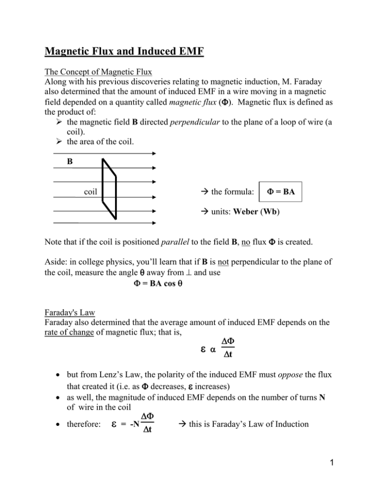
Magnetic Flux and Induced EMF The Concept of Magnetic Flux Along with his previous discoveries relating to magnetic induction, M. Faraday also determined that the amount of induced EMF in a wire moving in a magnetic field depended on a quantity called magnetic flux (Φ Φ). Magnetic flux is defined as the product of: the magnetic field B directed perpendicular to the plane of a loop of wire (a coil). the area of the coil. B the formula: coil Φ = BA units: Weber (Wb) Note that if the coil is positioned parallel to the field B, no flux Φ is created. Aside: in college physics, you’ll learn that if B is not perpendicular to the plane of the coil, measure the angle θ away from ⊥ and use Φ = BA cos θ Faraday's Law Faraday also determined that the average amount of induced EMF depends on the rate of change of magnetic flux; that is, ε α ∆Φ ∆t • but from Lenz’s Law, the polarity of the induced EMF must oppose the flux that created it (i.e. as Φ decreases, ε increases) • as well, the magnitude of induced EMF depends on the number of turns N of wire in the coil • therefore: ε = -N ∆Φ ∆t this is Faraday’s Law of Induction 1 Note that since Φ = BA, ∆Φ Φ = ∆BA or ∆Φ Φ = B∆A Substitute into Faraday’s Law formula as needed. Example #6: A coil of 150 turns and an area of 2.0 x 10⁻⁴ m2 is placed in a 1.00 T magnetic field as shown in the diagram below to the left. If this field changes to 0.45 T in 0.065 seconds, what is the average EMF induced in the coil and in what direction does the induced current flow? (see Induction Ex 6 for answer) Example #7: The magnitude of the ⊥ magnetic field through a 50 turn loop of wire changes from zero to 2.0 Wb/m2 is 0.20 seconds. The radius is 0.40 m and its electrical resistance is 5.0 Ω. a) Determine the magnitude of the average emf . b) Find the current in the loop. c) Determine the direction of the induced current in the loop if the loop is in the plane of the paper and the magnetic field is directed out of the paper. (see Induction Ex 7 for answer) 2 Note that the magnetic flux is the product of the area of the coil and the component of the magnetic field B directed ⊥ to the plane of the coil. Thus, a change in field strength ∆B can occur simply by turning the plane of the coil. A quarter turn situation is shown below: Using the formula Φ = BA where B is ⊥ to A, for the diagram on the left, the angle between the loop axis (dotted line) and the field is 0º, so that Φi = BA for the diagram on the right, the angle between the loop axis and the field is 90º, so that Φf = 0 This information can be used to solve for ∆Φ and subsequently ε using ε = -N ∆Φ ∆t 3 Example #8: A loop of 20 turns is 5 cm x 25 cm in area, and is turned onequarter turn from the starting position to the end position (as in the diagram on the previous page) in 0.30 seconds in a magnetic field B of 0.50 T. a) What average EMF was induced? b) What will the EMF be for the next 1/4 turn? (see Induction Ex 8 for answer) Note that the answers to Example #8 describe the way in which a generator creates voltage and alternating current (AC) electricity from the mechanical energy of a rotating armature. 4


