Surfaces: by definition Surfaces
advertisement
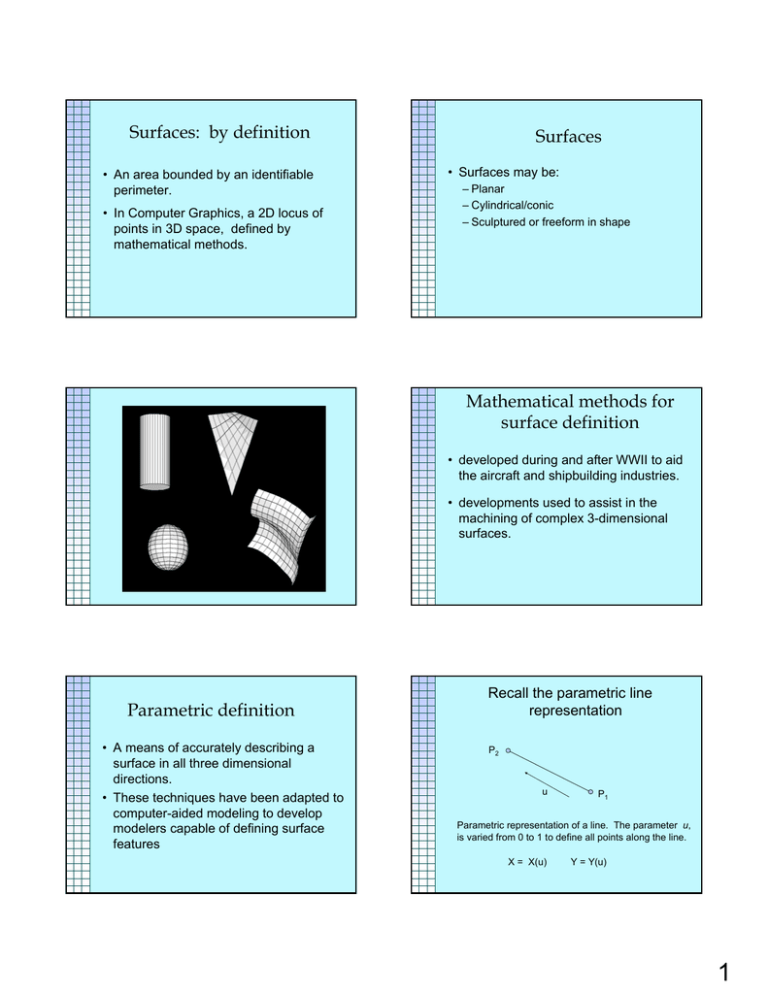
Surfaces: by definition • An area bounded by an identifiable perimeter. • In Computer Graphics, a 2D locus of points in 3D space, defined by mathematical methods. Surfaces • Surfaces may be: – Planar – Cylindrical/conic – Sculptured or freeform in shape Mathematical methods for surface definition • developed during and after WWII to aid the aircraft and shipbuilding industries. • developments used to assist in the machining of complex 3-dimensional surfaces. Parametric definition • A means of accurately describing a surface in all three dimensional directions. • These techniques have been adapted to computer-aided modeling to develop modelers capable of defining surface features Recall the parametric line representation P2 u P1 Parametric representation of a line. The parameter u, is varied from 0 to 1 to define all points along the line. X = X(u) Y = Y(u) 1 Bi-linear Surface Definition Points along edge P1 P2 have the form of P(u,0), along P3 P4 , P(u,1) and so on. Expanding the 2D parametric technique we used for a line to define a surface, two parameters (u and v) are used. P4 P(1,v) P4 P(u,1) P2 P2 P3 P(u,0) P3 v u P1 P(0,v) v u P1 By varying value of u and v, any point on the surface or the edge of the face may be defined. Curved Surface Patches P4 (u1,v1) P2 P3 v u P1 Surface Normal Vector • Planar surface on previous slides defined by first degree curves (first power functions of u and v) • For more complex surface shapes, higher order curves are used. • For example, a third order curve would use equations of the powers u1, u2, and u3. Surface Normal Vectors • A surface is defined by parametric equations in u and v. • Therefore at any given point there exist two tangent vectors (in u and v directions) 2 Surface Normal Vector Surface Normal at Given Point • The two tangent vectors define a tangent plane. • The vector perpendicular to this plane is the normal vector of the surface at that point. • It is determined by computing the cross product of the normal vectors. • A planar surface will have a single normal vector direction. Surface Curvature • Taking the derivative of the two tangent vectors at any given point yields values of local curvature. • Surface curvature is a measure of the rate-of-change of the curve slope. (how fast is the curve changing) Gaussian Curvature Surface Curvature • Surface curvature is an important aspect in design. – Provides an indication of smoothness (local creases and indentations) • Can be used to help in manufacturing. – Cutting tool size can be a function of maximum/minimum curvature For this surface… • At a point P on a surface, there will exist a Maximum and a Minimum curvature – (not necessarily in u and v directions) • The are referred to as the Principal Curvatures • The product of the Principal Curvatures is the Gaussian Curvature 3 Minimum and Maximum Curvatures Plot of Gaussian Curvature Gaussian Curvature Gaussian Curvature • Gaussian curvature can be a useful tool for finding surface inflections. • It indicates changes in surface direction. • Since Guassian curvature is the product of the principle curvatures: – For example, You can immediately spot a dent in the side of your car's door because it is an unwanted inflection in the surface, even if the surface is still tangent and curvature continuous. Saddle Point – For convex or concave surface, is has a positive value – For planar surfaces it has a value of zero – And, it has a negative value at a saddle point • One curvature is positive, the other negative Saddle Point 4 Surface definition • Ability to query database for surface information means: – possible to determine if a point lies off, on or on the boundary of a surface – often referred to as a “membership test” • data may be used for functions such as – rendering, manufacturing, surface area determination Faceted models • Some modelers limit model database or display representations to 1st order (planar) surface definitions • Surfaces of the model are represented by one or more planar polygons • Such models are known as polyhedral, polygonal or faceted models Faceted display and “smoothed” image Rendering • Results of membership test allow for the calculation of intersections between line of sight vectors and surface geometry. • This allows for the “depth sorting” of features – This is, which surfaces (or parts of surfaces) are visible from a particular line of sight Faceted models • Some modelers may store multiple databases (exact and approximate) and use faceted format for display only (to simplify display) • Display may be “cleaned-up” through rendering techniques. • Note that display alone does not indicate database storage Creating Surfaces • Complex shape generation facilitated through various methods • These methods permit complex surface generation through the use of defining parent geometry. • Parent geometry may be curves, vectors or specification data 5 Associativity • A dependency that exists between model entities • “child” entities are dependent upon their respective “parent geometry” • For surface construction: – Parent geometry required for surface creation – Surface cannot exist without parent geometry (cannot be deleted if associative) Surface of revolution Categorizations of complex surfaces: • • • • • surface of revolution tabulated cylinder ruled surface general sweep sculptured (Coons’ Patch) Surface of Revolution Profile • Requires: – a shape curve (must be continuous) – a specified angle – an axis defined in 3D modelspace. • Positive rotation direction usually based upon direction of axis vector. Axis of revolution Mathematic Definition of Surface of Revolution • Any point on surface is a function of two parameters, t and θ T describes the shape to be rotated θ represents the angle of rotation Z • Defined by projecting a shape curve (or profile) along a direction vector. • Curvature in one direction only (along shape curve), linear in other direction. Z Y Tabulated cylinder Y θ θ t t X X 6 Tabulated surface Shape curve (in bold) Vector Ruled surface Ruled surface • Linear interpolation between two bounding geometric elements (curves). • Elemental division the same for each curve. • Bounding curves must both be either geometrically open (line, arc) or closed (circle, ellipse). • Curvature in one direction only. General sweep • Shape curve (or profile) is swept along a path defined by an arbitrary curve. • Compare with: – Tabulated (path a vector) – Surface of revolution (path a single curve) Both geometries open (line & arc) Both geometries closed (circle & point*) • Shape curve and path for General Sweep. Sculptured surface (Coons’ patch) • Sometimes referred to as a “curvemesh” surface. • Most general of surface mesh definitions • Generated by interpolation across a set of defining shape curves • Resultant surface 7 Sculptured surface Some sculpted surfaces generated in a technique called lofting or blending. • A set of cross-sections curves are established. • The system will interpolate the crosssections to define a smooth surface geometry. • Shape curves through which Loft will be created. Surface Model Construction • Individual surfaces must be: • Resulting Lofted surface. Surface models • A significant improvement over wireframes – provide both visual and mathematical descriptions of model geometry. • More computationally expensive than wireframe models. – higher storage requirements, longer model regeneration time “intersected”, “trimmed”, “stitched” to one another to form a final shape May be a lack of connectivity between individual surfaces, e.g. tiny gaps, and overlaps between surfaces Surface Model Database • Permits direct assessment of certain model geometry such as: – Curve slope and curvature – Orientation of surface normal vectors – Surface curvature – Perimeter determination and surface area 8 Surface information: • allows points on the area of a surface to be mapped mathematically. – valuable in the generation of cutting tool paths for computer numerically controlled (CNC) machining operations. • used for the generation of visually realistic images through techniques such as Limitations of surface modeling techniques: • Does not represent internal features of the model, no sense of volume. • Models of limited value for volumetric and mass property analysis. – limited to certain shapes and features – rendering – hidden edge removal. Limitations of surface modeling techniques: Limitations of surface modeling techniques: • Connectivity • Possible to construct surfaces which intersect upon themselves • Multiple surfaces are needed to represent “real world” geometries. – Modeling software may not provide for adequate connectivity between these adjacent surfaces. – possibility exists for discontinuities at the intersections of adjacent surfaces. – no guarantee of continuity between adjacent surfaces • Model representation in this case is simply a collection of surfaces with no connectivity (topological) information. 9
