File
advertisement
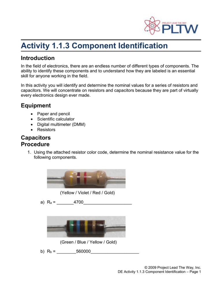
Activity 1.1.3 Component Identification Introduction In the field of electronics, there are an endless number of different types of components. The ability to identify these components and to understand how they are labeled is an essential skill for anyone working in the field. In this activity you will identify and determine the nominal values for a series of resistors and capacitors. We will concentrate on resistors and capacitors because they are part of virtually every electronics design ever made. Equipment Paper and pencil Scientific calculator Digital multimeter (DMM) Resistors Capacitors Procedure 1. Using the attached resistor color code, determine the nominal resistance value for the following components. (Yellow / Violet / Red / Gold) a) Ra = _______4700____________________ (Green / Blue / Yellow / Gold) b) Rb = ________560000____________________ © 2009 Project Lead The Way, Inc. DE Activity 1.1.3 Component Identification – Page 1 (Red / Violet / Brown / Gold) c) Rc = __________270__________________ (Brown / Red / Green / Gold) d) Rd = ___________1200000_________________ Resistor Re (Blue / Gray / Orange / Gold) e) Re = __________68000__________________ © 2009 Project Lead The Way, Inc. DE Activity 1.1.3 Component Identification – Page 2 2. Obtain 10 random resistors from your instructor. Using the Resistor Color Code Diagram, record each resistors nominal value and tolerance range. Next, use a digital multi-meter (DMM) to measure and record the actual resistance value of each resistor. Finally, indicate if the measured value is within acceptable tolerance. Resistor Colors Nominal Tolerance Range Value Nominal - % Measured Nominal +% Value Meets Tolerance? 1 Gry/r/y/gld 820000 779000 861000 840000 yes 2 Brn/blk/grn/gld 1000000 950000 1050000 1000000 yes 3 Ble/gry/y/gld 680000 646000 714000 697000 yes 4 Brn/grn/y/gld 150000 142500 157500 153000 yes 5 Grn/ble/y/gld 560000 532000 588000 556000 yes 6 Brn/blk/o/gld 10000 9500 10500 9880 yes 7 r/r/o/gld 22000 20900 23100 21800 yes 8 Gry/r/y/gld 820000 779000 861000 861000 yes 9 y/v/y/gld 470000 446500 493500 472000 yes 10 Brn/grn/o/gld 15000 14250 15750 14810 yes 3. Use the attached Disc Capacitor Label Diagram to determine the nominal capacitance value for the following components. a) Ca = __________47000 pF -20% +80%__________________ © 2009 Project Lead The Way, Inc. DE Activity 1.1.3 Component Identification – Page 3 b) Cb =________________470 uF____________ c) Cc = ____________220000________________ d) Cd = __________0.1 uF__________________ e) Ce = ____________1000________________ © 2009 Project Lead The Way, Inc. DE Activity 1.1.3 Component Identification – Page 4 Resistor Color Code Diagram Example : 270 Disc Capacitor Label Diagram © 2009 Project Lead The Way, Inc. DE Activity 1.1.3 Component Identification – Page 5 4 Fourth Tolerance Digit 7 First Digit Second Figure Second Digit First Figure 7 Third Digit 2 # of Zeros K 4 © 2009 Project Lead The Way, Inc. DE Activity 1.1.3 Component Identification – Page 6 Conclusion 1. Why are the measured values of the resistors different from the nominal values? 2. Identify each of the circled components for the printed circuit board shown below. A. ___________electrolytic capacitor _____________ B. _______diodes_________________ C. ____________8 pin solder socket____________ D. ____resistor____________________ E. ___Axial lead F. __Mylar / Tantalum Monolithic Ceramic G. LED_____________________ H. ___fuses___________________ I. _________transistor _______________ A 4 E D K 0 © 2009 Project Lead The Way, Inc. DE Activity 1.1.3 Component Identification – Page 7
