CH23-Circuits
advertisement
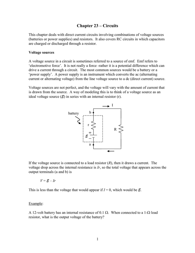
Chapter 23 – Circuits This chapter deals with direct current circuits involving combinations of voltage sources (batteries or power supplies) and resistors. It also covers RC circuits in which capacitors are charged or discharged through a resistor. Voltage sources A voltage source in a circuit is sometimes referred to a source of emf. Emf refers to ‘electromotive force’. It is not really a force -rather it is a potential difference which can drive a current through a circuit. The most common sources would be a battery or a ‘power supply’. A power supply is an instrument which converts the ac (alternating current or alternating voltage) from the line voltage source to a dc (direct current) source. Voltage sources are not perfect, and the voltage will vary with the amount of current that is drawn from the source. A way of modeling this is to think of a voltage source as an ideal voltage source (E) in series with an internal resistor (r). I b battery r R E a If the voltage source is connected to a load resistor (R), then it draws a current. The voltage drop across the internal resistance is Ir, so the total voltage that appears across the output terminals (a and b) is V = E – Ir This is less than the voltage that would appear if I = 0, which would be E. Example: A 12-volt battery has an internal resistance of 0.1 . When connected to a 1- load resistor, what is the output voltage of the battery? 1 Solution: The output voltage of the battery must be the same as the voltage across the load. So, V E-Ir IR I E 12V 10.9 A r R 0.1 1 V IR ( 10.9 A )( 1 ) 10.9V How much power is dissipated in the load? P I 2 R ( 10.9 A )2 ( 1 ) 119W How much power is dissipated internally in the battery? P ( 10.9 A )2 ( 0.1 ) 11.9W Resistor combinations For resistors in series, the current must be the same through each resistor, and the total voltage drop across the resistors is the sum of the voltage drop across each of the resistors. V V1 V2 V3 ... IRs I1R1 I 2 R2 I3 R3 ... I V I I1 I 2 I3 ... IRseries I( R1 R2 R3 ...) R1 V1 R2 V2 R3 V3 Rseries R1 R2 R3 .. I For resistors in parallel, the voltages must be the same across each resistor and the total current is the sum of the currents through each of the resistors. 2 V I1 I2 I3 R1 R2 R3 So, I I1 I 2 I3 ... V V1 V2 V3 ... R|| R1 R2 R3 V1 V2 V3 ... V 1 1 1 1 ... R|| R1 R2 R3 For two resistors in parallel, the above equation can be written as R|| R1R2 . R1 R2 Note that the rules for adding resistors in series and resistors in parallel are opposite to the rules for adding capacitors in series and in parallel. Example: Three resistors, R1 = 4 , R2 = 6 , and R3 = 12 , are connected in parallel. Find the equivalent resistance. Solution: 1 1 1 1 6 1 R|| 2 R|| 4 6 12 12 2 Note that R|| is smaller than any of the individual resistances. If connected in series, then the equivalent resistance is Rseries 4 6 12 22 Rseries is larger than any of the individual resistances. 3 Example: Find the current through and the voltage drop across each resistor in the circuit below. R1 =8 V =24 V R2 =6 R3 = 12 Solution: We first find the total equivalent resistance. R2 and R3 are in parallel, and this parallel combination is in series with R1. Thus, R23 R2 R3 ( 6 )( 12 ) 4 R2 R3 6 12 Req R1 R23 8 4 12 The total current, which is also the current through R1, is I V 24V 2 A ( I1 ) Req 12 Then, V1 I1R1 ( 2 A )( 8 ) 16V V2 V3 V23 IR23 ( 2 A )( 4 ) 8V V V 8V 8V I2 2 1.33 A, I3 3 0.67 A R2 6 R3 12 Note that, as required, I1 I 2 I3 V1 V23 V 4 Kirchoff’s Rules In the previous problem we saw that the currents at the junction of the resistors added and that the voltages across the resistors added to give the supply voltage. These are very general results and apply to all circuits. They are referred to as Kirchoff’s rules: 1. The sum of the currents entering a junction must be the sum of the currents leaving a junction. (junction rule) 2. The sum of the potential changes around a closed loop must add to zero. (loop rule) The first rule is based on conservation of charge and the second rule is based on conservation of energy. In interpreting and applying the loop rule, we have to be careful about signs. V can be positive or negative, depending on whether V increases or decreases while traversing the loop across a circuit element. Example: Let’s apply the loop rule to the simple series circuit below. b V =9V R1 =1 V1 =3V R2 =2 V2 =6V c a We must first pick a direction (clockwise or counter-clockwise) about which to traverse the loop in summing the potential changes. Either direction will work. As indicated above, we choose the clockwise direction. Starting at point a, applying the loop rule gives V IR1 IR2 0 We can solve this for I and get I = 9V/3 = 3 A. Then, 9V ( 3 A )( 1 ) ( 3 A )( 2 ) 9V 3V 6V 0 In going from point a to point b, the potential increases. In going from b to c the potential decreases. (Current flows in the direction of decreasing potential.) And in going from c back to a, the potential also decreases. If we had summed the potential 5 changes going counter-clockwise, all the signs in the above equation would have been reversed, but the results would have been the same. Kirchoff’s rules can be helpful in determining the currents and voltages in complex multiloop circuits. Example: Use Kirchoff’s rules to determine the current in each part of the circuit below. b R1 =2 V1 = 12 V I1 R2 =3 I2 I3 V2 =6V R3 =6 a Solution: Applying the loop rule in the clockwise direction to the left loop, starting from point a, we have V1 I1R1 I 2 R2 V2 0 12V I1( 2 ) I 2 ( 3 ) 6V 0 Dropping the units and simplifying, the above equation is 2I1 3I 2 6 Eq. (1) Note that the sign of the potential change when going across a resistor depends on whether we are going in the direction of the current (-) or opposite to the current (+). For the right loop, starting from a and going clockwise, we have V2 I 2 R2 I3 R3 0 6V I 2 ( 3 ) I3( 6 ) 0 Again, dropping units and simplifying, we have I 2 2I 3 2 Eq. (2) 6 The sum rule, applied to either junction a or b, gives I1 I 2 I 3 Eq. (3) The three boxed equations involve three unknowns, I1, I2, and I3. We can solve these equations to get (do the algebra) I1 = 2 A, I2 = -0.67 A, I3 = 1.33 A Note that the sign of I2 is negative. This means that the choice of the direction of I2 indicated in the diagram (up) was reversed. The current is really down. Capacitor Combinations Circuits can have multiple capacitors. In the simplest configurations, the capacitors would be either in parallel, in series, or in a combination of series and parallel. Capacitors in parallel In the parallel circuit, the electrical potential across the capacitors is the same and is the same as that of the potential source (battery or power supply). This is because the capacitors and potential source are all connected by conducting wires which are assumed to have no electrical resistance (thus no potential drop along the wires). The two capacitors in parallel can be replaced with a single equivalent capacitor. The charge on the equivalent capacitor is the sum of the charges on C1 and C2. (This is the meaning of equivalent.) Thus, Q Q1 Q2 C||V C1V1 C2 V2 Since V = V1 = V2, then C|| C1 C2 V C1 Q1 C2 Q2 V 7 Q C|| Capacitors in series In the series circuit, the potential of the source is the sum of the potentials across C1 and C2. This is a consequence of conservation of energy. (A test charge moved across the source must have the same change in potential energy as a test charge moved across C1 and then across C2.) The charges on each capacitor are the same (since each charge comes from the potential source). Also, the charge on each capacitor is the same as the charge on the single equivalent capacitor, Cseries. Thus, V V1 V2 Q Q1 Q2 C s C1 C 2 Or, since Q = Q1 = Q2, 1 1 1 C s C1 C 2 Another way of writing this equation is Cs C1C2 C1 C 2 Q1 V C1 C2 Q2 V1 V Cs Q V2 For more than two capacitors in parallel or in series, the addition equations are C|| C1 C2 C3 ... 1 1 1 1 ... C s C1 C 2 C3 8 RC Circuits Charging a capacitor When a capacitor is charged through a resistor, then the voltage across the capacitor and the charge on the capacitor will increase exponentially in time, as shown in the graph to the right. When the voltage across the capacitor reaches the battery voltage, then it will stop charging. VC E R E 0.63 E I C = RC t The time dependence of the capacitor voltage and charge are given by VC E ( 1 e t / RC ) , q CVC CE ( 1 e t / RC ) where e (= 2.718…) is the base of the natural logarithm. We can evaluate VC at some relevant times: t = 0, VC E ( 1 e 0 ) E ( 1 1 ) 0 . t = , VC E ( 1 e ) E ( 1 0 ) E t = RC, VC E ( 1 e 1 ) E ( 1 0.368...) 0.632E RC has units of time and is a measure of how long it takes for the capacitor to charge through the resistor. (Actually, it takes an infinite time to fully charge; however, it charges up to nearly 2/3 its final value (0.632…) in the time RC.) The current through the resistor is greatest when the charging starts and decreases exponentially in time and approaches zero as the capacitor voltage reaches the battery voltage. I I 0 e t / RC If the capacitor is initially uncharged, then the initial current is 9 I0 E R The sum of the voltages across the battery, resistor and capacitor add to zero: E -iR-Vc 0 By substitution, it can be shown that the exponential expressions for I and Vc satisfy this equation. Discharging a capacitor When a capacitor is discharged through a resistor, then its voltage and charge decrease exponentially in time. VC V0 R I 0.368 V0 C = RC VC V0 e t / RC , t q CVC CV0 e t / RC The discharge current is opposite to the charge current and its magnitude also decreases exponentially. Evaluating VC at some relevant times, we have t = 0, VC V0 e 0 V0 . t = , VC V0 e 0 t = RC, VC V0 e 1 0.368V0 Example: A 10-F capacitor is charged by a 24-volt battery through a 400-k resistor. After 1 s, what is the voltage across the capacitor, the charge on the capacitor, the current to the capacitor, and the voltage across the resistor? Solution: 10 The time constant is = RC = (400 x 103 )(10 x 10-6 F) = 4 s VC E ( 1 e t / RC ) 24V ( 1 e 1 / 4 ) 24V ( 1 0.779 ) 5.3V q CVC ( 10 x10 6 F )( 5.3V ) 5.3 x10 5 C I E t / RC 24V e e 1 / 4 4.57 x10 5 A 5 R 4 x10 V R IR ( 4.57 x10 5 A )( 4 x10 5 ) 18.7 V Note that VC + VR = E . Example: A 2 F-capacitor is charged to 50 volts and then discharged through a 1 M resistor. Find the time for the capacitor voltage to drop to 25 volts. Solution: VC V0 e t / RC 25V 50Ve t / RC e t / RC 25 / 50 0.5 t ln( e t / RC ) ln( 0.5 ) ln( 2 ) RC t RC ln( 2 ) ( 1x10 6 )( 2 x10 6 F ) ln( 2 ) 1.39 s 11
