Forced oscillation - Pohl’s pendulum
with measure Dynamics
TEP
Related topics
Angular velocity, characteristic frequency, resonance frequency, torsional pendulum, torsional oscillation,
restoring torque, damped/undamped free oscillation, forced oscillation, ratio of damping/decrement, constant damping, logarithmic decrement, aperiodic case, and creeping
Principle
If an oscillating system is allowed to oscillate freely, we can observe that the decrement of successive
maximum amplitudes strongly depends on the damping value. If the oscillating system is caused to oscillate by an external torsional oscillation, we can observe that the amplitude in a stationary state is a function of the frequency and amplitude of the external periodic torsional oscillation and of the damping value. The aim of this experiment is to determine the characteristic frequency of the free oscillation as well
as the resonance curve of a forced oscillation.
Equipment
1
1
1
1
2
2
3
1
torsional pendulum (after R.W. Pohl)
ariable transformer, 25 V AC/20 V DC, 12 A
bridge rectifier, 30 V AC/1 A DC
digital multimeter
connecting cords, l = 250 mm, yellow
connecting cords, l = 750 mm, red
connecting cords, l = 750 mm, blue
"measure Dynamics" software
11214-00
13531-93
06031-10
07129-00
07360-02
07362-01
07362-04
14440-61
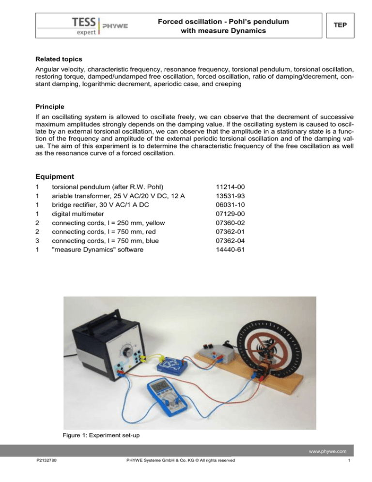
Figure 1: Experiment set-up
www.phywe.com
P2132780
PHYWE Systeme GmbH & Co. KG © All rights reserved
1
TEP
Forced oscillation - Pohl’s pendulum
with measure Dynamics
Additional material:
Coloured, circular disc, video camera, tripod, computer
Tasks
A. Free oscillation
1. Determination of the period of oscillation and
characteristic frequency for the undamped
case.
2. Determination of the period of oscillation and
corresponding characteristic frequencies for
various damping values. Calculation of the
corresponding ratios of damping, damping
constant, and logarithmic decrement.
3. Realisation of the aperiodic case and creeping case.
B. Forced oscillation
1. Determination of the resonance curve and
graphical representation of the resonance
curve by way of the damping values of A.
2. Observation of the phase difference be- Figure 2: Power connection for the experiment
tween the torsional pendulum and the exciting, external rotation for a small damping
value with different excitation frequencies.
Set-up
Set the experiment up as shown in Figures 1 and 2.
Connect the DC output of the variable transformer
to the eddy current brake. The excitation motor also
requires DC voltage, which is why a bridge rectifier
must be connected between the AC output (12 V) of
the variable transformer and the excitation motor
(DC motor, see Figure 3). Connect the DC current
IB, which supplies the eddy current brake, via the
adjusting knob of the variable transformer and
check it by way of an ammeter.
In terms of the video that will be recorded, the folFigure 3: Connection of the excitation motor (DC motor)
lowing must be taken into consideration concerning
to the variable transformer
the setting and positioning of the camera:
Set the number of frames per second to approximately 30 fps.
Select a light-coloured, homogeneous background.
Provide additional lighting for the experiment.
The experiment set-up, i.e. Pohl's pendulum, should be in the centre of the video. To ensure this,
position the video camera on a tripod centrally in front of the experiment set-up. For the experiment concerning the forced oscillations, however, it is important that the excitation motor is also
filmed. However, the pendulum must remain in the centre of the video.
The experiment set-up should fill the video image as completely as possible.
2
PHYWE Systeme GmbH & Co. KG © All rights reserved
P2132780
Forced oscillation - Pohl’s pendulum
with measure Dynamics
TEP
The optical axis of the camera must be parallel to
the experiment set-up.
For the video analysis, we recommend gluing a
circular, coloured sheet of paper onto the rotating
needle of the pendulum (see Figure 4).
Measure the width of the pendulum for scaling.
Then, the video recording process and the experiment
can be started.
Procedure
A. Free oscillation
Figure 4: Pendulum pointer in the zero position
1. Determination of the period of oscillation and characteristic frequency for the undamped case.
In order to determine the characteristic frequency ω0 of the torsional pendulum without damping (IB = 0),
- start the video recording process,
- deflect the pendulum completely in one direction,
- measure the time that is needed for several oscillations, and
- stop the video recording process.
2. Determination of the period of oscillation and corresponding characteristic frequencies for various
damping values.
Prior to starting the experiment, it must be ensured that the pointer of the pendulum at rest coincides
with the zero position of the scale (see Figure 4). This can be achieved by manually turning the eccentric
disc of the motor.
In the same manner as for A1, the characteristic frequencies for damped oscillations must be determined. These frequencies are caused by the following currents flowing through the eddy current brake:
𝐼𝐵 ~ 0.45 A
𝐼𝐵 ~ 0.80 A
The damping values can then be determined based on the recorded video.
3. Realisation of the aperiodic case and creeping case.
Adjust these currents in order to realise the aperiodic case (IB ~ 2.0 A) and the creeping case (IB ~ 2.3 A).
The rest of the experiment procedure is the same as for A1 and A2.
Caution: Current intensities above 2.0 A must not be used for more than a few minutes for the eddy current brake!
www.phywe.com
P2132780
PHYWE Systeme GmbH & Co. KG © All rights reserved
3
Forced oscillation - Pohl’s pendulum
with measure Dynamics
TEP
B. Forced oscillation
In order to excite the torsional pendulum, the connecting rod of the motor must be fastened to the upper
third of the source of excitation. The excitation frequency 𝜔𝑎 can be determined by determining the time
that is required for several rotations of the motor in the video.
1. Determination of the resonance curves and graphical representation of the resonance curves by way
of the damping values of A.
The (continuous) video recording process begins with low excitation frequencies ωa. Then, increase ωa
first with the "coarse" motor potentiometer. Close to the maximum of ωa, vary the excitation frequency in
small steps with the "fine" motor potentiometer (see Figure 5). In each case, ensure that the pendulum
amplitude is stable prior to varying the excitation frequency. In the case of a pendulum movement without damping or with only very small damping values, the excitation frequency ωa must be chosen so that
the pendulum does not exceed its maximum deflection.
2. Observation of the phase difference between the torsional pendulum and the exciting, external rotation for a small damping value with different excitation frequencies.
Choose a small damping value and excite the pendulum with a frequency ωa far below and then far
above the resonance frequency. Record these processes by way of the video camera.
A. Undamped and damped free oscillation
Theory
In the case of a free, damped torsional oscillation, the torques M1 (spiral spring) and M2 (eddy current
brake) act upon the pendulum. We have
𝑀1 = −𝐷 0 ϕ 𝑎𝑛𝑑 𝑀2 = −𝐶Φ̇
Φ = angle of rotation
𝛷̇ = rotational velocity
D0 = rotation per unit angle
C = proportionality factor, depending on the currents that
flow through the eddy current brake
The resulting torque
𝑀1 = −𝐷 0 ϕ − 𝐶ϕ
leads us the following equation of motion:
𝐼ϕ̈ + C = Φ + 𝐷 0 ϕ = 0
(1)
(1)
I = moment of inertia of the pendulum
ϕ̈ = angular acceleration
4
Figure 5: Control knobs for adjusting the excitation frequency.
Upper knob: "coarse"; lower knob: "fine".
PHYWE Systeme GmbH & Co. KG © All rights reserved
P2132780
Forced oscillation - Pohl’s pendulum
with measure Dynamics
TEP
Dividing equation (1) by I and using the abbreviations
𝛿=
𝐶
𝐷0
𝑎𝑛𝑑 𝜔02 =
2𝐼
𝐼
results in
ϕ̈ + 2δϕ + ω20 ϕ = 0
(2)
δ is known as the "damping constant" and
𝐷0
𝜔0 = √
𝐼
is the characteristic frequency of the undamped system. The solution of the differential equation (2) is
𝜙(𝑡) = 𝜙0 𝑒 −𝛿𝑡 cos 𝜔𝑡
(3)
𝜔 = √𝜔02 − 𝛿 2
(4)
with
Evaluation
Transfer the various videos that have been recorded to the computer. Then, start "measure Dynamics"
and open the video under "File" – "Open video ...". Mark the start of the experiment ("Start selection" and
"Time zero") and the end of the experiment ("End selection") in the video for further analysis via the
menu line above the video. The experiment begins when the torsional pendulum is released and it ends
when the video ends. Mark the width of Pohl's pendulum with the scale that appears in the video by way
of "Video analysis" – "Scaling ..." – "Calibration" and enter the measured length (in this case 0.30 m) into
the input window. In addition, enter the frame rate that has been set for the recording process under
"Change frame rate" and position the origin of the system of coordinates in the centre of rotation of the
pendulum under "Origin and direction".
Then, the actual motion analysis can be started under "Video analysis" – "Automatic analysis" or "Manual analysis". For the automatic analysis, we recommend selecting "Motion and colour analysis" on the
"Analysis" tab. Under "Options", the automatic analysis can be optimised, if necessary, e.g. by changing
the sensitivity or by limiting the detection radius. Then, look for a film position in the video where the object that is to be analysed is perfectly visible. Click the object. If the system recognises the object, a
green rectangle appears and the analysis can be started by clicking "Start".
If the automatic analysis does not lead to any satisfying results, the series of measurements can be corrected under "Manual analysis" by manually marking the object that is to be analysed.
www.phywe.com
P2132780
PHYWE Systeme GmbH & Co. KG © All rights reserved
5
TEP
Forced oscillation - Pohl’s pendulum
with measure Dynamics
Task A1: Determination of the period of oscillation and characteristic frequency for the undamped case.
In order to determine the average period of oscillation 𝑇̅0 and the corresponding characteristic frequency
𝜔0 of the free and undamped, oscillating torsional pendulum, we have to determine the time that the
pendulum needs for several oscillations (e.g. 10 oscillations). This leads to:
𝑇0 = 1.962 s
and
1
𝜔0 = 3.20 ∙ .
s
Task A2: Determination of the period of oscillation and corresponding characteristic frequencies for various damping values. Calculation of the corresponding ratios of damping, damping constant, and logarithmic decrement.
The average period of oscillation 𝑇̅0 and the average frequency 𝜔0 are determined in the same manner
as for task 1. For 𝐼𝐵,1 = 0.45 A, this leads to
𝑇̅0,1 = 1.946 s
𝜔
̅0,1 = 3.23 ∙ 1⁄s
For 𝐼𝐵,2 = 0.80 A, this leads to
𝑇̅0,2 = 1.935 s
𝜔0,2 = 3.25 ∙ 1⁄s
Then, perform a graphical representation of the maximum amplitudes on one side of the pendulum, i.e.
always on the right-hand side or always on the left-hand side of the pendulum, as a function of time. Add
a new column to the worksheet by clicking "New column" in the table menu line. Enter "Phi" (unit: "°";
formula: "arctan2(x;y)*360/(2*π)") into this new column. Then, create another column (name: "Phi_max";
unit: "°"). Find the various maxima of "Phi" in the table and enter the values of "Phi" of these maxima into
the column "Phi_max". In order to display the maxima of "Phi" as a function of time, select "Display" and
"Diagram", click "Options", delete all of the already existing graphs, and select the graphs t (horizontal
axis) – "Phi_max" (vertical axis). For 𝐼𝐵,1 = 0.45 A, this leads to:
6
PHYWE Systeme GmbH & Co. KG © All rights reserved
P2132780
Forced oscillation - Pohl’s pendulum
with measure Dynamics
TEP
Figure 6: Representation of the maximum deflections of the pendulum for 𝐼𝐵,1 = 0.45 A on one side as a function of
time t
Figure 7: Representation of the maximum deflections of the pendulum for 𝐼𝐵,2 = 0.80 A on one side as a function of
time t
For 𝐼𝐵,2 = 0. 80 A, this leads to:
We already know from the theory – and Figures 6 and 7 confirm this – that a higher current 𝐼𝐵 causes
the torsional pendulum to be decelerated more quickly.
www.phywe.com
P2132780
PHYWE Systeme GmbH & Co. KG © All rights reserved
7
Forced oscillation - Pohl’s pendulum
with measure Dynamics
TEP
The resulting relationship between damping, damping constant K, and logarithmic decrement Λ is calculated as follows:
Equation (3) shows that the amplitude 𝜙(𝑡) of the damped oscillation decreases to the eth part of the initial amplitude 𝜙0 after the time 𝑡 = 1⁄𝛿. Equation (3) also shows that the ratio of two successive amplitudes is constant.
𝜙𝑛
= 𝐾 = 𝑒 𝛿𝑇
𝜙𝑛+1
(5)
K is known as the damping constant or "damping ratio", 𝑇 as the period of oscillation, and
Λ = ln 𝐾 = 𝛿𝑇 = ln
𝜙𝑛
𝜙𝑛+1
(6)
as the "logarithmic decrement". This leads to:
Table 1:
I/A
0.45
0.80
1
/s
𝛿
4.6
1.5
𝛿/s −1
𝜔 = √𝜔02 − 𝛿 2 /s
0.22
0.67
3.21
3.27
𝜙𝑛
𝜙𝑛+1
1.54
3.72
𝐾=
Λ
0.43
1.31
The difference of the values for the frequency 𝜔 is due to the fact that 𝛿 can be determined only in a rather imprecise manner. Still, the calculated frequencies are nearly consistent with the measured frequencies.
Task A3: Realisation of the aperiodic case and creeping case.
Add a new column with the name "Phi" to the table in the same manner as for task A2. Select "Display"
Figure 8: Representation of the deflections of the pendulum for 𝐼𝐵 = 2.00 A as a function of time t
8
PHYWE Systeme GmbH & Co. KG © All rights reserved
P2132780
Forced oscillation - Pohl’s pendulum
with measure Dynamics
TEP
and "Diagram", click "Options", delete all of the already existing graphs, and select the graphs t (horizontal axis) – "Phi" (vertical axis). This leads to:
According to the theory, equation (4) has a real solution only if 𝜔02 ≥ 𝛿 2 . For 𝜔02 = 𝛿 2 , the pendulum returns to its initial position very quickly without oscillation (aperiodic case, see Figure 8). For 𝜔02 < 𝛿 2 , the
Figure 9: Representation of the deflections of the pendulum for 𝐼𝐵 = 2.30 A on one side as a function of time t
pendulum returns to its initial position in an asymptotic manner (creeping case, see Figure 9).
B. Forced oscillation
Theory
If the pendulum is subject to a periodic torque 𝑀𝑎 = 𝑀0 cos 𝜔𝑎 𝑡 , equation (2) changes to
ϕ̈ + 2δϕ + ω20 ϕ = F0 cos ωa t
where 𝐹0 =
𝑀0
.
𝐼
(7)
In the stationary state, the solution of the differential equation is
𝜙(𝑡) = 𝜙𝑎 𝑐𝑜𝑠(𝜔𝑎 𝑡 − 𝛼)
(8)
with
𝜙𝑎 =
𝜙0
2
2 2
√{1−[𝜔𝑎 ] } +[2 𝛿 𝜔𝑎 ]
𝜔0
𝜔0 𝜔0
(9)
F
and 𝜙𝑎 = ω02
0
Furthermore,
www.phywe.com
P2132780
PHYWE Systeme GmbH & Co. KG © All rights reserved
9
Forced oscillation - Pohl’s pendulum
with measure Dynamics
TEP
2δω
tan α = ω2 −ωa2
0
a
and also
α = arc tan
(10)
2δωa
.
ω20 − ω2a
Evaluation
Task B1: Determination of the resonance curve and graphical representation of the resonance curve by
way of the damping values of A.
For this task, we recommend performing the analysis of the rotational motion manually, since only a few
moments of the video area actually relevant for the evaluation. Add new columns for "Phi" (see task A2),
for the period of oscillation "T" (unit: "s"), and for the excitation frequency "wa" (unit: "1/s", formula:
"2*π/T")) to the worksheet. It may be necessary to add a minus sign to the formula when creating the
"Phi" column so that the values become positive. Then, determine the excitation frequency (in the same
manner as for task A1, but in this case observe the eccentric disc and not the pendulum). Wait until the
torsional pendulum has developed a constant amplitude and mark the pendulum at the maximum in the
manual analysis. Enter the period of oscillation, which has already been determined, into the same line
under "T". Do the same for the other excitation frequencies.
In order to display the maximum deflection "Phi" as a function of the excitation frequency, select "Display" and "Diagram", click "Options", delete all of the already existing graphs, and select the graphs (horizontal axis) – "Phi" (vertical axis). This leads to:
Figure 10: Resonance curve for 𝑰𝑩 = 𝟎. 𝟐𝟑 𝐀
Figure 10 shows that the amplitude is very small in the case of low excitation frequencies. When the excitation frequency is slowly increased, a maximum can be observed. Increasing the excitation frequency
further leads to smaller amplitudes until the amplitude drops nearly to 0. This is the characteristic shape
10
PHYWE Systeme GmbH & Co. KG © All rights reserved
P2132780
Forced oscillation - Pohl’s pendulum
with measure Dynamics
TEP
of a resonance curve. The relatively sharp maximum of the amplitude occurs at the so-called resonance
frequency. Here, the resonance frequency is ω = 3.20 1⁄𝑠. In addition, it becomes clear that the resonance frequency matches the characteristic frequency of the torsional pendulum, which has been determined in task A1. This gives rise to the suspicion that ϕ → ϕmax für ωa ≅ ω0 . If one considers equation
(9), this suspicion is confirmed by the theory. For higher damping values, the curve is above the represented curve, and it is below the represented curve for smaller damping values.
Task B2: Observation of the phase difference between the torsional pendulum and the exciting, external
rotation for a small damping value with different excitation frequencies.
For this task, the video of task B1 is required. If we observe the torsional pendulum for a lower excitation
frequency 𝜔𝑎 , it becomes clear that there is no phase difference between the torsional pendulum and
exciting pendulum, i.e. the pendulum and the exciting torque are "in phase". If the excitation frequency
𝜔𝑎 is much higher than the resonance frequency 𝜔0 , the pendulum and the exciting torque show a phase
difference π, i.e. they are in "antiphase" with each other. If the resonance frequency is applied to the torsional pendulum, the phase difference is 𝜋⁄2. The smaller the damping value is, the quicker is the transition from "in phase" oscillation to "antiphase" oscillation.
Figure 11: Phase difference in the case of a forced oscillation
for different damping values
www.phywe.com
P2132780
PHYWE Systeme GmbH & Co. KG © All rights reserved
11
TEP
Forced oscillation - Pohl’s pendulum
with measure Dynamics
Space for notes:
12
PHYWE Systeme GmbH & Co. KG © All rights reserved
P2132780


