LIMITERS AND CLAMPERS
advertisement
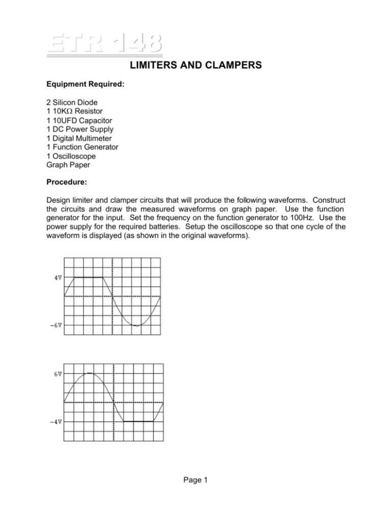
ETR 148 LIMITERS AND CLAMPERS Equipment Required: 2 Silicon Diode 1 10KΩ Resistor 1 10UFD Capacitor 1 DC Power Supply 1 Digital Multimeter 1 Function Generator 1 Oscilloscope Graph Paper Procedure: Design limiter and clamper circuits that will produce the following waveforms. Construct the circuits and draw the measured waveforms on graph paper. Use the function generator for the input. Set the frequency on the function generator to 100Hz. Use the power supply for the required batteries. Setup the oscilloscope so that one cycle of the waveform is displayed (as shown in the original waveforms). Page 1 ETR 148 Page 2 ETR 148 Multisim: Use Multisim to analyze 1 clipper and 1 clamper circuit. When doing the transient analysis on the clamper, set the start time to 20 seconds and the stop time to 20.01. This allows the capacitor time to charge. You may also need to connect a 1 MegΩ resistor across the output. Print the output waveform for each. Page 3

