Advanced Electronic Platform Technologies Supporting
advertisement
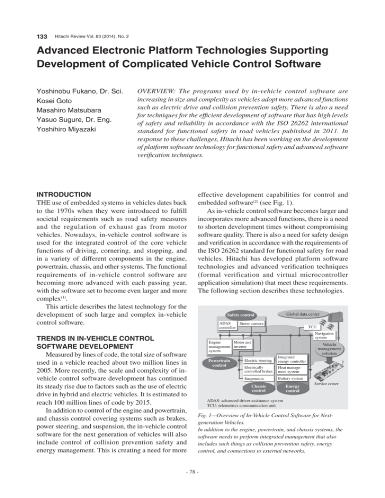
133 Hitachi Review Vol. 63 (2014), No. 2 Advanced Electronic Platform Technologies Supporting Development of Complicated Vehicle Control Software Yoshinobu Fukano, Dr. Sci. Kosei Goto Masahiro Matsubara Yasuo Sugure, Dr. Eng. Yoshihiro Miyazaki OVERVIEW: The programs used by in-vehicle control software are increasing in size and complexity as vehicles adopt more advanced functions such as electric drive and collision prevention safety. There is also a need for techniques for the efficient development of software that has high levels of safety and reliability in accordance with the ISO 26262 international standard for functional safety in road vehicles published in 2011. In response to these challenges, Hitachi has been working on the development of platform software technology for functional safety and advanced software verification techniques. INTRODUCTION THE use of embedded systems in vehicles dates back to the 1970s when they were introduced to fulfill societal requirements such as road safety measures and the regulation of exhaust gas from motor vehicles. Nowadays, in-vehicle control software is used for the integrated control of the core vehicle functions of driving, cornering, and stopping, and in a variety of different components in the engine, powertrain, chassis, and other systems. The functional requirements of in-vehicle control software are becoming more advanced with each passing year, with the software set to become even larger and more complex(1). This article describes the latest technology for the development of such large and complex in-vehicle control software. TRENDS IN IN-VEHICLE CONTROL SOFTWARE DEVELOPMENT Measured by lines of code, the total size of software used in a vehicle reached about two million lines in 2005. More recently, the scale and complexity of invehicle control software development has continued its steady rise due to factors such as the use of electric drive in hybrid and electric vehicles. It is estimated to reach 100 million lines of code by 2015. In addition to control of the engine and powertrain, and chassis control covering systems such as brakes, power steering, and suspension, the in-vehicle control software for the next generation of vehicles will also include control of collision prevention safety and energy management. This is creating a need for more effective development capabilities for control and embedded software(2) (see Fig. 1). As in-vehicle control software becomes larger and incorporates more advanced functions, there is a need to shorten development times without compromising software quality. There is also a need for safety design and verification in accordance with the requirements of the ISO 26262 standard for functional safety for road vehicles. Hitachi has developed platform software technologies and advanced verification techniques (formal verification and virtual microcontroller application simulation) that meet these requirements. The following section describes these technologies. Global data center Safety control ADAS Stereo camera controller TCU Navigation system Engine Motor and management inverter system Powertrain control Vehicle management solution Electric steering Integrated energy controller Electrically controlled brakes Heat management system Suspension Battery system Chassis control Energy control Service center ADAS: advanced driver assistance system TCU: telemetrics communication unit Fig. 1—Overview of In-Vehicle Control Software for Nextgeneration Vehicles. In addition to the engine, powertrain, and chassis systems, the software needs to perform integrated management that also includes such things as collision prevention safety, energy control, and connections to external networks. - 78 - Hitachi Review Vol. 63 (2014), No. 2 Application (components) RTE Hitachi’s standard platform software Platform software customized for product (Complex Drivers) FR SPI CAN MEM DIAG SYS COM AUTOSAR OS PLATFORM SOFTWARE TECHNOLOGIES FOR FUNCTIONAL SAFETY Hitachi Automotive Systems, Ltd. is working on standard software platforms for significantly shortening the time taken to develop embedded software for vehicles while also reducing its cost and achieving higher reliability. Hitachi’s standard platform software for compliance with functional safety standards and industry standardization [such as the Automotive Open System Architecture (AUTOSAR)] (see Fig. 2) can run on the microcontrollers used mainly for powertrain systems such as the engine or inverter, and for brakes and other chassis systems. The structure of the standard platform software is based on the industry standard AUTOSAR specification (ICC1). Also, application layer software developed by Hitachi’s customers or its product design departments interfaces with the platform software via a run-time environment (RTE). Accordingly, by complying with the RTE interface specifications, the application layer software can minimize the influence of differences in hardware such as the choice of microcontroller or the circuit design of control units. Also, to ensure the general applicability of the platform software, it has a layer structure in which the microcontroller and other hardware factors are hidden by the low-level microcontroller abstraction layer (MCAL). For compliance with functional safety standards, the development process conforms to automotive safety integration level (ASIL) D stipulated by ISO 26262 to ensure that the platform software can be used for products with any safety level. Implementing a freedom from interference (FFI) function is an important technology for complying with functional safety standards. The FFI function applies to situations when software with different safety levels (ASILs) coexists on the same microcontroller and prevents dependent failures propagating from software with a low ASIL to software with a high ASIL. While the platform software developed by Hitachi has the highest ASIL-D level, the embedded application software used in vehicles may have various different levels, such as ASIL-A or ASIL-B, or may be subject to quality management (QM) that is outside the scope of functional safety. Accordingly, the following protection functions are incorporated into the platform software to prevent the propagation of dependent failures from software with safety levels other than ASIL-D. 134 MCAL Microcontroller RTE: run-time environment AUTOSAR: Automotive Open System Architecture OS: operating system MCAL: microcontroller abstraction layer CAN: controller area network SYS: system DIAG: diagnosis MEM: memory COM: communications SPI: serial peripheral interface FR: FlexRay Fig. 2—Overview of Hitachi’s Standard Platform Software. The product-specific application layer is at the top and the platform software layer (standard software platform) at the bottom, with the RTE in between. (1) Timing protection This mainly involves using AUTOSAR operating system (OS) functions to monitor the timing of tasks and interrupts. Hitachi has also added functions it has developed itself to strengthen protection. (2) Memory protection (memory partitioning) T h i s u s e s t h e AU TO S A R O S a n d t h e microcontroller’s memory protection functions to protect the ASIL-D areas of memory. Hitachi has developed a high-speed memory partitioning technique that minimizes the overhead associated with switching the program execution mode between ASIL-D and other safety levels (context switching). FORMAL VERIFICATION The ISO 26262 standard for functional safety for road vehicles recommends the use of formal verification for ASIL-C and ASIL-D systems that have particularly high safety requirements. Hitachi has incorporated one such formal verification technique, called model checking, into its products to maintain and improve the reliability of vehicle software as it becomes increasingly large and complex. The motivation is to reduce the level of software defects to near zero by comprehensively testing all test paths through the source code as well as the conventional testing method of comparing the output produced by a particular input with the expected output. - 79 - 135 Advanced Electronic Platform Technologies Supporting Development of Complicated Vehicle Control Software Formal verification uses a precisely defined language to represent the requirements and associated design, and can verify that the two match through the use of mathematical theory. In the case of model checking, this verification is performed automatically. Model checking works by using a model of the software design and having a computer rigorously work through the potential states that can arise when the software is executing to determine whether there are any operations that are not in the specifications (operations that were not foreseen in the design process). The problem with this approach, however, arises when the number of software states is very large and the computer does not have enough resources to check them all. Despite improvements in computer performance, the scope of application for model checking has remained limited and its use on the large software used in production products has been problematic for many years. To implement a practical form of formal verification (model checking), Hitachi has developed a technique that significantly reduces the number of states in the check model by analyzing the dependencies between variables that appear in the source code to identify which code is relevant to the variables in the software being checked, and then converting this into the check model (see Fig. 3). By doing so, Hitachi has succeeded in applying model checking to the complete software for electronic control units, even though such software may consist of as many as several hundred thousand lines(3). The size of the software being checked is approximately 10 times larger than other examples reported in the literature. The reasons why checking can be performed for such large program sizes is that the analysis technique features precision and high speed (100,000 lines or so of code can be analyzed in a few minutes on a standard PC), and because means have been provided for the software developers to select check points or adjust the range of software selected for conversion based on their design knowledge. Variable dependencies can be plotted on a graph to provide the software developers with visual ways of adjusting the scope of model conversion. This technique was used to produce a tool to help with checking that makes the work more efficient by automatically generating the check model from the software’s source code (4). This provides the infrastructure for applying formal methods (model checking) to product developments with the ASIL-C or ASIL-D level. Hitachi is proceeding with its progressive introduction. VIRTUAL MICROCONTROLLER APPLICATION SIMULATION TECHNIQUE This section describes the use of a virtual microcontroller application simulation technique for testing in-vehicle control software without the target hardware. Vehicle control system Tool for automatic generation of validation model Source code C programming language Exclude code with no links to check point. Variable Dependency Control 1 OS Reduce number of states to make validation possible. Defect Control 2 Diagnostics Application interface I/O Communications Platform software System being controlled Check model Hardware Model validation units Adjust scope Start Conversion Selection Control 1 Check point variables Control 2 Select check points and limit scope. Software designer Defect path Interrupt Interrupt Control 1 Stop engine I/O: input/output Fig. 3—Technique for Automatic Generation of Validation Model from Source Code. Check point variables are those that are potentially affected by a defect. The tool automatically determines the links between these variables and other variables (dependencies) and identifies the relevant code with a high degree of precision. The software designers can also use their design knowledge to limit the scope of the source code to be converted to a model. Together, these techniques produce a model that can be used for validation. - 80 - Hitachi Review Vol. 63 (2014), No. 2 Block diagram of simulation with virtual microcontroller used for ACC system 136 Comparison of simulation results ACC ECU System being controlled (CoMET R ) 01001010 01101011 11101010 01010111 Inputs 6,000 Control software (production code) M32R CPU Event processor MJT Vehicle model Main microcontroller ICU I/F Virtual CAN bus (CoMET) CoMET MATLAB I/F CAN ADC I/O port Engine speed (rpm) (MATLAB/Simulink) 3,000 HILS 0 30 0 30 60 (s) 6,000 3,000 vHILS vCAN bus Sub-microcontroller Memory 60 (s) ACC: adaptive cruise control ECU: electronic control unit CPU: central processing unit MJT: multi-junction timer ICU: interrupt control unit ADC: analog/digital converter HILS: hardware-in-the-loop simulation vHILS: virtual HILS I/F: interface * CoMET is a trademark or registered trademark of Synopsys Inc. Fig. 4—Application of Simulation with Virtual Microcontroller to ACC System. Validation of control software at the production code level was successfully conducted without using the target hardware by performing a joint simulation combining the MATLAB/Simulink models for the systems being controlled with the CoMET models for CAN communications and the ECU containing the microcontrollers. The conventional practice for validating control software at the production code level in the past was to use hardware-in-the-loop simulation (HILS). This involved connecting the actual microcontroller hardware to a simulator that modeled the behavior of the system being controlled. However, use of the actual hardware brings with it practical restrictions. In response, Hitachi has developed virtual HILS (vHILS) to allow validation of control software without the target hardware. This uses a joint simulation consisting of a virtual microcontroller and a model of the system being controlled(5), (6), (7). vHILS can be used for validating control software at the production code level. The main benefits are, (1) software validation can be performed at times and places where the microcontroller and other parts of the target system are not available, and (2) faster validation achieved by performing large numbers of tests concurrently, which is made possible by the ease with which the validation environment can temporarily be replicated. The vHILS technique was applied to an adaptive cruise control (ACC) system (see Fig. 4). The ACC system maintains a safe following distance behind the vehicle ahead by controlling the engine, brake, and other systems based on the distance to the other vehicle and its relative speed acquired using an external recognition sensor. The new validation system reused the MATLAB*/Simulink* models used in HILS for the electronic control units (ECUs) and the engine, brake, and other vehicle systems that they control. New models were produced, however, for the main microcontroller, sub-microcontroller, and memory in the ACC ECU, and for the controller area network (CAN) communications it uses to connect to other ECUs. In the case of CAN communications, the speed of simulation was increased without compromising accuracy by simulating the message-level communications, which is all that is needed to test the control software. The same test cases used for the previous HILS testing were repeated on the vHILS system and the simulation accuracy and execution speed were assessed. The results shown in Fig. 4 indicate agreement for the logical operations such as the vehicle engine speeds and the speed change timings. Although equivalent accuracy was achieved, the execution speed was only 34% that of HILS. This indicates that equivalence with the target system can be achieved using a three-node configuration by executing a number of tests concurrently. Validation processing performance superior to HILS was also demonstrated by increasing the number of computing nodes. Results have also been obtained indicating that the amount of work required for pre-delivery testing can be reduced to 1/20 to 1/400 that of HILS by implementing the means to execute software validation automatically using cloud computing(7). * MATLAB and Simulink are registered trademarks of The MathWorks, Inc. of the USA. - 81 - 137 Advanced Electronic Platform Technologies Supporting Development of Complicated Vehicle Control Software To promote the wider adoption of the vHILS technique described above through collaboration at all levels of the industry with an interest in vHILS (automotive manufacturers, parts makers, simulation tool vendors, semiconductor manufacturers, and research institutions), the Virtual ECU Model-Based Development (vECU-MBD) Working Group has been set up at the Japan Virtual Microcontroller Initiative (JVMI)(8). CONCLUSIONS This article has described platform software development technologies and advanced validation techniques for the next generation of in-vehicle control software development. Hitachi Automotive Systems, Ltd. is working with the research divisions of Hitachi to devise platform technologies for in-vehicle control software development that extend beyond those described in this article. By integrating the technologies described here, Hitachi will be able to establish advanced development processes for the next generation of invehicle control software. REFERENCES (1) S. Kawana, “Current Status of Automotive Software Development (Software Engineering for Embedded System),” IPSJ Magazine 45, No. 7, pp. 713–715 (Jul. 2004) in Japanese. (2) “Growing Use of Simulation Technology in Automotive Software Development,” Nikkei Automotive Technology (27), pp. 68–73 (Nov. 2011) in Japanese. (3) Hitachi News Release, “Development of Highly Reliable Verification Technology for Automotive Control Software Using Formal Methods” (Apr. 2013) http://www.hitachi.co.jp/ New/cnews/month/2013/04/0416a.html in Japanese. (4) M. Matsubara et al., “Application of Model Checking to Automotive Control Software with Slicing Technique,” SAE 2013 World Congress (2013-01-0436), (Apr. 2013). (5) Y. Ito et al., “VIRTUAL HILS: A Model-Based Control Software Validation Method,” SAE 2011 World Congress (2011-01-1018), Int. J. Passeng. Cars -Electron. Electr. Syst. 4 (1):142-149 (Apr. 2011). (6) Y. Sugure et al., “Failure Mode and Effects Analysis Using Virtual Prototyping System with Microcontroller Model for Automotive Control System,” 7th IFAC Symposium on Advances in Automotive Control (Sept. 2013). (7) Hitachi News Release, “Development of Fully Virtual Simulation Technique for Railway, Automotive, and Other Embedded Software that Does not Require Actual System” (Oct. 2010) http://www.hitachi.co.jp/New/cnews/ month/2010/10/1028.html in Japanese. (8) vECU-MBD Working Group, http://www.vecu-mbd.org/en/ ABOUT THE AUTHORS Yoshinobu Fukano, Dr. Sci. Kosei Goto System Development Engineering Department, Technology Development Division, Hitachi Automotive Systems, Ltd. He is currently engaged in the development of model-based development technology for the in-vehicle control software development process. Dr. Fukano is a member of the Association for Computing Machinery (ACM) and the Society of Automotive Engineers of Japan (JSAE). Electric Platform Development Department, Technology Development Division, Hitachi Automotive Systems, Ltd. He is currently engaged in the development of standardized basic software. Mr. Goto is a member of the JSAE. Masahiro Matsubara Yasuo Sugure, Dr. Eng. GM4 Unit, Department of Green Mobility Research, Hitachi Research Laboratory, Hitachi, Ltd. He is currently engaged in the development of verification techniques for automotive control software. Mr. Matsubara is a member of the Information Processing Society of Japan (IPSJ). Platform Systems Research Department, Central Research Laboratory, Hitachi, Ltd. He is currently engaged in research of virtual prototyping systems using microcontroller models for automotive control systems. Dr. Sugure is a member of the Society of Automobile Engineers (SAE) and The Institute of Electronics, Information and Communication Engineers (IEICE). Yoshihiro Miyazaki Technology Development Division, Hitachi Automotive Systems, Ltd. He is currently engaged in the development of electronic platform technology for invehicle control systems. Mr. Miyazaki is a member of The Institute of Electrical Engineers of Japan (IEEJ), IPSJ, and JSAE. - 82 -


