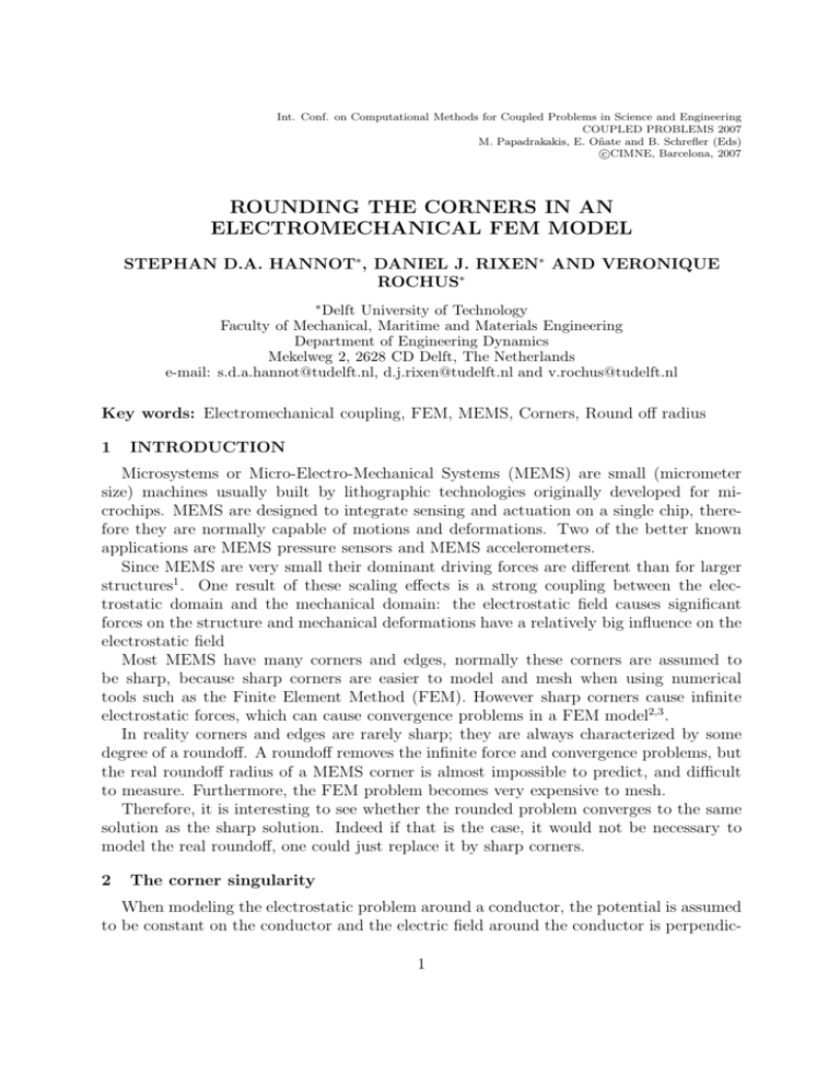
rounding the corners in an electromechanical fem model
advertisement

Int. Conf. on Computational Methods for Coupled Problems in Science and Engineering COUPLED PROBLEMS 2007 M. Papadrakakis, E. Oñate and B. Schrefler (Eds) c CIMNE, Barcelona, 2007 ROUNDING THE CORNERS IN AN ELECTROMECHANICAL FEM MODEL STEPHAN D.A. HANNOT∗, DANIEL J. RIXEN∗ AND VERONIQUE ROCHUS∗ ∗ Delft University of Technology Faculty of Mechanical, Maritime and Materials Engineering Department of Engineering Dynamics Mekelweg 2, 2628 CD Delft, The Netherlands e-mail: s.d.a.hannot@tudelft.nl, d.j.rixen@tudelft.nl and v.rochus@tudelft.nl Key words: Electromechanical coupling, FEM, MEMS, Corners, Round off radius 1 INTRODUCTION Microsystems or Micro-Electro-Mechanical Systems (MEMS) are small (micrometer size) machines usually built by lithographic technologies originally developed for microchips. MEMS are designed to integrate sensing and actuation on a single chip, therefore they are normally capable of motions and deformations. Two of the better known applications are MEMS pressure sensors and MEMS accelerometers. Since MEMS are very small their dominant driving forces are different than for larger structures1 . One result of these scaling effects is a strong coupling between the electrostatic domain and the mechanical domain: the electrostatic field causes significant forces on the structure and mechanical deformations have a relatively big influence on the electrostatic field Most MEMS have many corners and edges, normally these corners are assumed to be sharp, because sharp corners are easier to model and mesh when using numerical tools such as the Finite Element Method (FEM). However sharp corners cause infinite electrostatic forces, which can cause convergence problems in a FEM model2,3 . In reality corners and edges are rarely sharp; they are always characterized by some degree of a roundoff. A roundoff removes the infinite force and convergence problems, but the real roundoff radius of a MEMS corner is almost impossible to predict, and difficult to measure. Furthermore, the FEM problem becomes very expensive to mesh. Therefore, it is interesting to see whether the rounded problem converges to the same solution as the sharp solution. Indeed if that is the case, it would not be necessary to model the real roundoff, one could just replace it by sharp corners. 2 The corner singularity When modeling the electrostatic problem around a conductor, the potential is assumed to be constant on the conductor and the electric field around the conductor is perpendic1 Stephan D.A. Hannot, Daniel J. Rixen and Véronique Rochus ular to the boundary. Near a corner, the field is perpendicular on both sides leading to a corner and at the corner the electric field has a sudden change in direction. This results in a peak of electric charge at that corner, which causes an infinite force on an infinitesimal part of the conductor2 . 3 Modeling the electromechanical coupling using FEM To model the electromechanical coupling using FEM, the electrostatic forces have to be computed and added to the mechanical problem. The usual approach is to use a local function of the electric field E to describe the electrostatic force4 : 1 F es = ε0 E 2 n̄ 2 (1) In this equation F es is the electrostatic distributed boundary force, ε0 is the permittivity of the electrostatic domain, E 2 is the square of the electric field normal to the surface and n̄ is the unit normal vector. Another method to compute the electrostatic force is the variational method which uses a variation of the total electromechanical energy in an element to derive the nodal forces. These forces are computed by the following equation for the 2D case (but this expression also exists for the 3D case)5 : ∂φ Z ∂φ ∂φ 1 0 2 − T ∂X ∂Y ∂X F es = ε0 E BdΩ (2) ∂φ ∂φ ∂φ − ∂Y 2 ∂X 0 2 Ω ∂Y here is φ the electric potential field, E is the electric field and B contains the derivatives of the shape functions of the displacement field. The right-hand side has to be integrated over the volume of the element Ω to compute the electrostatic forces. 3.1 Application to a simple corner The geometric singularities might cause convergence problems for the electrostatic force computation, because a converged solution for the potential does not mean that the forces have converged3 . Therefore, to estimate the severeness of the convergence problem, a single corner has been modeled. The geometry is shown in figure 1: a unit square conductor on the bottom right part of model, surrounded by an air gap. The total size of the model is 2m by 2m, the relative permittivity of the air is assumed to be 1. The conductor is grounded, the opposing top and left-hand boundaries have been given a unit potential. The right-hand and bottom boundaries are assumed to represent symmetry condition, Neumann conditions are applied on them. The convergence ratio is determined for both FEM approaches. The corner is meshed with a number of square elements with linear shape functions. The element size is decreased, thus the number of elements is increased. The respective solutions are given in 2 Stephan D.A. Hannot, Daniel J. Rixen and Véronique Rochus 1 0.95 0.9 x 0 |F /ε | 0.85 0.8 0.75 0.7 0.65 Local force function Variational 0.6 0.55 0 10 20 30 40 50 1/h Figure 1: Potential field around a sharp corner Figure 2: Convergence for both the variational and local force approaches figure 2. Here the x-axis denotes 1/h, with h the size of an element, the y-axis denotes the absolute value for the force in x-direction divided by the permittivity in a vacuum. In the figure it can be seen that only the variational approach (2) yields a converged solution before computation times become too large. 4 Rounding the corners One standard method to overcome these convergence problems consists in rounding off the corners6 . In that case the singularity is smoothed, thus the charge peak at the corner remains bounded, hence there is a finite force peak at the corner. However one big disadvantage of a rounded corner is related to the mesh near a corner. To accurately mesh the curved geometry, a much higher number of elements is required compared to the sharp corner. Another difficulty is that the magnitude of the radius has to be chosen. In reality sharp corners hardly ever exist, there is always some degree of a round off. However it is nearly impossible to predict this real radius beforehand or to measure each individual edge on a fabricated MEMS. When the corner is rounded, also the local force approach (1) converges to a final solution. To see if rounded corner solution converges to the sharp corner solution with decreasing radii, the same corner is investigated. The results are summarized in figure 3. The x-axis signifies the inverse radius 1/r and the y-axis the electrostatic force in the xdirection, obtained for a converged mesh. It is clear that the force in not really influenced by the rounding radius and converges to the same value as the variational solution for a sharp corners. With a round off radius of r = 1/10 on a corner with unit sides, the relative error is only 1%. 3 Stephan D.A. Hannot, Daniel J. Rixen and Véronique Rochus x 0 |F /ε | 1 0.98 0.96 0.94 0 50 1/r 100 Figure 3: Electrostatic forces for different rounding radii 5 CONCLUSIONS 1. The variational approach is much more suited to model sharp corners than the local force approach, only when the corners are rounded the local force approach can solve the problem, but at the expense of the extra elements to mesh the curve. 2. The computed force does not really vary with the radius, therefore if the corners can be modeled with sharp elements it is much more efficient to use them in combination with the variational approach even if in reality there is a round off radius. Therefore it is not necessary to predict or measure the real radius, saving time. 6 Acknowledgements We acknowledge the financial support of the MicroNed program of the Ministry of Economic Affairs of the Netherlands. The third author acknowledges the financial support of the Belgian National Fund for Scientific Research. REFERENCES [1] M. Wautelet. Scaling Laws in the Macro-, Micro- and Nanoworlds. European J. Phys., 22, 601–611, (2001). [2] D.J. Griffiths, Introduction to Electrodynamics, Prentice-Hall, (1989). [3] Comsol Multiphysics User’s Guide, version 3.3, Comsol AB, (2006). [4] V. Rochus, D.J. Rixen and J.C. Golinval. Monolithical Modeling of the ElectroMechanical coupling in Micro-Structures. Int. J. Num. Meth. Engng., 65, 461–493, (2006). [5] E.T. Ong, K.H. Lee and K.M. Lim. Singular Elements For Electro-mechanical Coupling Analysis of Micro-devices. J. Micromech. Microeng., 13, 482–490, (2003). [6] Y. Zhao and T. Cui. Fabrication of High-aspect-ratio Polymer-based Electrostatic Comb Drives using the Hot Embossing Technique. J. Micromech. Microeng., 13, 430–435, (2003). 4


