Section #23 38 13 - Commercial Kitchen Hoods
advertisement
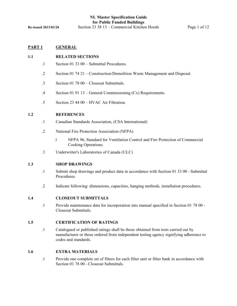
NL Master Specification Guide for Public Funded Buildings Section 23 38 13 – Commercial Kitchen Hoods Re-issued 2013/02/28 PART 1 GENERAL 1.1 RELATED SECTIONS Page 1 of 12 .1 Section 01 33 00 – Submittal Procedures. .2 Section 01 74 21 – Construction/Demolition Waste Management and Disposal. .3 Section 01 78 00 – Closeout Submittals. .4 Section 01 91 13 – General Commissioning (Cx) Requirements. .5 Section 23 44 00 – HVAC Air Filtration. 1.2 REFERENCES .1 Canadian Standards Association, (CSA International) .2 National Fire Protection Association (NFPA) .1 .3 1.3 NFPA 96, Standard for Ventilation Control and Fire Protection of Commercial Cooking Operations. Underwriter's Laboratories of Canada (ULC) SHOP DRAWINGS .1 Submit shop drawings and product data in accordance with Section 01 33 00 - Submittal Procedures. .2 Indicate following: dimensions, capacities, hanging methods, installation procedures. 1.4 CLOSEOUT SUBMITTALS .1 1.5 Provide maintenance data for incorporation into manual specified in Section 01 78 00 Closeout Submittals. CERTIFICATION OF RATINGS .1 1.6 Catalogued or published ratings shall be those obtained from tests carried out by manufacturer or those ordered from independent testing agency signifying adherence to codes and standards. EXTRA MATERIALS .1 Provide one complete set of filters for each filter unit or filter bank in accordance with Section 01 78 00 - Closeout Submittals. NL Master Specification Guide for Public Funded Buildings Section 23 38 13 – Commercial Kitchen Hoods Re-issued 2013/02/28 1.7 Page 2 of 12 WASTE MANAGEMENT AND DISPOSAL .1 Separate and recycle waste materials in accordance with Section 01 74 21 Construction/Demolition Waste Management and Disposal. .2 Divert unused metal and wiring materials from landfill to metal recycling facility approved by Owner’s Representative. .3 Remove from site and dispose of packaging materials at appropriate recycling facilities. .4 Dispose of corrugated cardboard, polystyrene, plastic, packaging material in appropriate on-site bin for recycling in accordance with site waste management program. 1.8 TRAINING .1 Provide training in accordance with Section 01 91 41 – Commissioning (Cx) Training. PART 2 PRODUCTS 2.1 RANGE HOOD - DOMESTIC .1 Complete system including: .1 .2 .3 .4 .5 .6 750 or 900 mm hood as indicated. Lifetime washable aluminum filter. Light unit with bulb. Centrifugal, twin blower and two speed motor. Fan and light switches. Colored to be selected by Owner’s Representative. .2 Roof or wall outlet complete with backdraft damper as indicated. .3 Capacity: see schedule on drawings. Noise rating: vertical discharge max 6 sones horizontal discharge max 7 sones .4 2.2 Acceptable Product: Broan, Nutone. WASH DOWN GREASE EXTRACTOR TYPE .1 General: .1 .2 .3 .4 Cyclonic motion of air through extraction chamber and continuous cold water mist spray grease extractor, hot water detergent wash down. Configuration as indicated. Complete with back panel on wall mounted units. ULC label, CSA seal. NL Master Specification Guide for Public Funded Buildings Section 23 38 13 – Commercial Kitchen Hoods Re-issued 2013/02/28 .5 .2 .3 Manual stop-start at hood. 24h 7 day program timer for cleaning cycle. Panel 1.2 mm type 304 stainless steel, hinged cover. Selector switches, pilot lights for run and wash. Detergent container. Shut off valves Hot water solenoid Detergent pump Relay timer Wash time delay Hot water line strainer Cold water pressure reducing valve and solenoid valve Pressure gauge Cold water line strainer Panel completely prewired. Cleaning system: .1 .2 .6 Self-closing fire damper UCL Listed, in duct collar. Control system: .1 .2 .3 .4 .5 .6 .7 .8 .9 .10 .11 .12 .13 .14 .15 .5 Type 304 stainless steel. Finishes: .1 Exposed stainless steel surfaces to be No.4 brushed satin finish. .2 Accessories to be stainless steel or polished chrome plate. Stainless steel facia panels, as indicated. Fire detection and suppression system: see Section 21 23 00 – Wet Chemical Fire Extinguishing Systems. .1 .4 Flush mounted fluorescent fixture(s) 914 mm or 1219 mm long (2 x 40 watts) include lamps, pre-wired to junction box. Materials: .1 .2 .3 Page 3 of 12 Nozzle type detergent spray cleaning system. System to conform to Sanitary Standards of Food and Beverage Industry 3A and United States Public Health Service (USPHS) standards. Performance: .1 .2 .3 .4 400 L/s-m of active length for wall type. 800 L/s-m of active length for island type. Pressure drop max through unit up to duct collar: 375 Pa. Length mm, width mm, height mm: information on drawings. Re-issued 2013/02/28 2.3 NL Master Specification Guide for Public Funded Buildings Section 23 38 13 – Commercial Kitchen Hoods Page 4 of 12 BOX STYLE HOOD WITHOUT MAKEUP AIR .1 Ventilator construction of stainless steel with UL/ULC listed filters. Ventilator provided with stainless steel all welded exhaust duct collar with a 25 mm connection flange. All joints and seams welded and/or liquid tight. All exposed welds ground and polished to the original finish of metal. .2 Hanging brackets supplied on each unit for ceiling or wall mount installations. .3 Ventilators equipped with UL/ULC listed self-closing, spring loaded fire damper assembly activated by listed fusible link, rated at (141o C). .4 UL/ULC listed air balancing damper provided for balancing of single and multiple ventilator systems. All dampers accessible through ventilator plenum. .5 Ventilators listed by Underwriters Laboratories and/or Underwriters Laboratories of Canada and meet all NFPA 96 requirements. .6 HOOD SIZE – LENGTH , WIDTH , HEIGHT : information on drawings. SERVICES – EXHAUST AIR: information on drawings.. STATIC PRESSURE: information on drawings. COLLAR SIZE: information on drawings. ELECTRICAL: 120/1/60, WATT: information on drawings. DIRECT CONNECT TO JUNCTION BOX(ES) : FOR LIGHTS, information on drawings. .7 Flush mounted fluorescent light fixture(s) 914 mm or 1219 mm long (2 x 40 watts) include lamps. .8 Fire detection and suppression system: see Section 21 23 00 – Wet Chemical Fire Extinguishing Systems. 2.4 BOX STYLE HOOD WITH MAKEUP AIR .1 Ventilator construction of stainless steel. With ventilator provided with stainless steel all welded exhaust duct collar with a 25 mm connection flange. All joints and seams welded and/or liquid tight. All exposed welds ground and polished to the original finish of metal. .2 Hanging brackets supplied on each unit for ceiling or wall mount installations. .3 Ventilators will be equipped with UL/ULC listed self-closing, spring loaded fire damper assembly activated by a listed fusible link, rated at 141 o C. .4 UL/ULC listed air balancing damper provided for balancing of single and multiple ventilator systems. All dampers accessible through the ventilator plenum. Re-issued 2013/02/28 NL Master Specification Guide for Public Funded Buildings Section 23 38 13 – Commercial Kitchen Hoods Page 5 of 12 .5 Integrated make-up air plenum located at the front of the ventilator. Make-up air discharged through perforated stainless steel panels. .6 Ventilators listed by Underwriters Laboratories and/or Underwriters Laboratories of Canada and meet all NFPA 96 requirements. .7 HOOD SIZE – LENGTH .8 SERVICES – EXHAUST AIR: information on drawings. , WIDTH , HEIGHT ,: information on drawings. STATIC PRESSURE: information on drawings. COLLAR SIZE: information on drawings. ELECTRICAL: 120/1/60, WATT: information on drawings. DIRECT CONNECT TO JUNCTION BOX(ES)FOR LIGHTS: information on drawings. .9 Flush mount fluorescent light fixture 914 mm or 1219 mm long (2 x 40 watts), include lamps. .10 Fire detection and suppression system: see Section 21 23 00 – Wet Chemical Fire Extinguishing Systems. 2.5 LOW PROFILE STYLE HOOD .1 Ventilator construction of stainless steel with UL/ULC listed filters. The ventilator provided with stainless steel all welded exhaust duct collar with a 25 mm connection flange. All joints and seams welded and/or liquid tight. All exposed welds ground and polished to the original finish of metal. .2 Hanging brackets supplied on each unit for ceiling or wall mount installations. .3 Ventilators equipped with UL/ULC listed self-closing, spring loaded fire damper assembly activated by a listed fusible link, rated at 141 o C. .4 UL/ULC listed air balancing damper provided for balancing of single and multiple ventilator systems. All dampers accessible through the ventilator plenum. .5 Ventilators listed by Underwriters Laboratories and/or Underwriters Laboratories of Canada and meet all NFPA 96 requirements. .6 HOOD SIZE – LENGTH .7 SERVICES – EXHAUST AIR: information on drawings. , WIDTH , HEIGHT STATIC PRESSURE: information on drawings. COLLAR SIZE: information on drawings. : information on drawings. Re-issued 2013/02/28 NL Master Specification Guide for Public Funded Buildings Section 23 38 13 – Commercial Kitchen Hoods Page 6 of 12 ELECTRICAL: 120/1/60, WATT: information on drawings.. DIRECT CONNECT TO JUNCTION BOX(ES) , FOR LIGHTS: information on drawings. .8 Fire detection and suppression system: see Section 21 23 00 – Wet Chemical Fire Extinguishing Systems. BOX STYLE HOOD WITHOUT MAKEUP AIR – UV TECHNOLOGY 2.6 .1 Ventilator with UV light source technology which self cleans the hood interior. Hood to have a UL/ULC listing. Light source designed specifically for grease extraction. .2 Ventilator complete with control panel with a kitchen exhaust fan on/off switch, alarm reset push-button, alarm buzzer and lamps to indicate Power on, Maintenance Required, Access Open, No Airflow and Fire. A text read-out screen indicating total hours of operation and system status provided within the panel. A logic board interlock to be provided. .3 The ventilator constructed of stainless steel with UL/ULC listed cartridge filters, and provided with stainless steel all welded exhaust duct collar with 25 mm connection flange. All joints and seams welded and/or liquid tight. All exposed welds ground and polished to the original finish of metal. Full length hanging bracket supplied on each ventilator for ceiling or wall mount installations. .4 Ventilators equipped with a UL/ULC listed self-closing, spring loaded fire damper assembly activated by a listed fusible link, rated at 141 o C. .5 An adjustable UL/ULC listed exhaust air volume control damper provided for balancing of single and multiple ventilator installations, all dampers accessible through the ventilator plenum. .6 HOOD SIZE – LENGTH .7 SERVICES – EXHAUST AIR: information on drawings. , WIDTH , HEIGHT : information on drawings. STATIC PRESSURE: information on drawings. COLLAR SIZE: information on drawings. ELECTRICAL: 120/1/60, WATT: information on drawings. DIRECT CONNECT TO JUNCTION BOX(ES) FOR LIGHTS: information on drawings. .8 Flush mount fluorescent light fixture 914 or 1219 mm long (2 x 40 watts), include lamps for light fixture(s). .9 Stainless steel main back – where exposed, for island applications. Re-issued 2013/02/28 .10 2.7 NL Master Specification Guide for Public Funded Buildings Section 23 38 13 – Commercial Kitchen Hoods Page 7 of 12 Fire detection and suppression system: see Section 21 23 00 – Wet Chemical Fire Extinguishing Systems. BOX STYLE HOOD WITH MAKEUP AIR, UV GREASE EXTRATION .1 Ventilator with UV light source technology which self cleans the hood interior. Hood to have a UL/ULC listing. Light source designed specifically for grease extraction. .2 Ventilator complete with control panel with a kitchen exhaust fan on/off switch. Alarm reset push-button, alarm buzzer and lamps to indicate Power on, Maintenance Required, Access Open, No airflow and Fire. Text read-out screen indicating total hours of operation and system status provided within the panel. A logic board interlock to be provided. Electrical supply 120/1/60. .3 Ventilator constructed of stainless steel with UL/ULC listed cartridge filters with a stainless steel all welded exhaust duct collar with 25 mm connection flange. All joints and seams welded and/or liquid tight. All exposed welds ground and polished to the original finish of metal. Full length hanging bracket supplied on each ventilator for ceiling or wall mount installations. .4 Ventilators equipped with a UL/ULC listed self-closing, spring loaded fire damper assembly activated by a listed fusible link, rated at 141 o C. An adjustable UL/ULC listed exhaust air volume control damper provided for balancing of single and multiple ventilator installations, all dampers accessible through the ventilator plenum. .5 Integrated make-up air plenum located at the front of the ventilator. Make-up air discharged through perforated stainless steel panels. .6 HOOD SIZE – LENGTH .7 SERVICES – EXHAUST AIR: information on drawings. , WIDTH , HEIGHT: information on drawings. STATIC PRESSURE: information on drawings. COLLAR SIZE: information on drawings. ELECTRICAL: 120/1/60, WATT: information on drawings. .8 DIRECT CONNECT TO JUNCTION BOX(ES) FOR LIGHTS: information on drawings. .9 Flush mount fluorescent light fixture 1219 mm long (2 x 40 watts), include lamps. .10 Fire detection and suppression system: see Section 21 23 00 - Wet Chemical Fire Extinguishing Systems. 2.8 LOW PROFILE STYLE HOOD UV GREASE EXTRACTION .1 Ventilator with UV light source technology which self cleans the hood interior. Hood to have a UL/ULC listing. Light source designed specifically for grease extraction. Re-issued 2013/02/28 NL Master Specification Guide for Public Funded Buildings Section 23 38 13 – Commercial Kitchen Hoods Page 8 of 12 .2 Ventilator complete with control panel with a kitchen exhaust fan on/off switch, alarm reset push-button, alarm buzzer and lamps to indicate Power On, Maintenance Required, Access Open, No Airflow and Fire. A text read-out screen indicating total hours of operation and system status provided within the panel. A logic board interlock to be provided. Electrical supply 120/1/60. .3 Ventilator constructed of stainless steel with UL/ULC listed cartridge filters and with stainless steel all welded exhaust duct collar with 25 mm connection flange. All joints and seams welded and/or liquid tight. All exposed welds ground and polished to the original finish of metal. Full length hanging bracket supplied on each ventilator for ceiling or wall mount installations. .4 Ventilators equipped with a UL/ULC listed self-closing, spring loaded fire damper assembly activated by a listed fusible link, rated at 141 o C. An adjustable UL/ULC listed exhaust air volume control damper provided for balancing of single and multiple ventilator installations, all dampers accessible through the ventilator plenum. .5 HOOD SIZE – LENGTH .6 SERVICES – EXHAUST AIR: information on drawings. .7 STATIC PRESSURE: information on drawings. .8 COLLAR SIZE: information on drawings. .9 ELECTRICAL: 120/1/60, WATT: information on drawings. .10 DIRECT CONNECT TO JUNCTION BOX(ES) FOR LIGHTS listed: information on drawings. .11 STAINLESS STEEL MAIN BACK - Where exposed, for island applications. .12 Fire detection and suppression system: see Section 21 23 00 – Wet Chemical Fire Extinguishing Systems. 2.9 , WIDTH , HEIGHT : information on drawings. CAPTURE JET HOOD .1 Supply and install kitchen exhaust hood as indicated. The hood to bear the intertek E.T.L. label, comply with standard 710, and be fabricated in accordance with NFPA-96. .2 Construction: .1 .2 .3 Kitchen hood inner liner to be constructed from 1.2 mm stainless steel where exposed. Kitchen hood to be supplied complete with outer casing/main body, inner liner, exhaust duct, pressure measurement T.A.B ports. Outer casing panels to be constructed of stainless steel with a brushed satin finish. Each joint to be welded and liquid tight, avoiding harmful dripping of condensation. All exposed welds ground and polished to the original finish of metal. Canopy ends to be double sided wall construction (no single wall hoods permitted). Re-issued 2013/02/28 NL Master Specification Guide for Public Funded Buildings Section 23 38 13 – Commercial Kitchen Hoods Page 9 of 12 .3 Exhaust airflow to be based on convective heat generated by the appliances underneath each hood system. Submittals to include convective heat calculations based on the input power of the appliance served. .4 Hood to be designed with capture jet technology to reduce the exhaust airflow rate required, and to improve capture and containment efficiency of hood, while reducing energy consumption. The capture jet air to be introduced through a special discharge panel and shall not exceed 10% of the calculated exhaust airflow. The capture jet discharge velocity to be a minimum of 7.62 m/s. The capture jet to be internally mounted with a speed control. Fire damper or electronic shut down in fire mode not required. .5 Airflow through the extractors and capture jet air chamber shall be determined through the integral T.A.B. (Testing and Balancing) ports mounted in the hood. Airflows to be determined by the pressure vs. airflow curves supplied by the manufacturer. .6 Hood to be equipped with multi-cyclone stainless steel grease extractors. Filters to be NSF and UL Classified. Grease extraction efficiency to be 93% on particles with a diameter of 5 microns and 98% on particles with a diameter of 15 microns or larger as tested by an independent testing laboratory. Pressure loss over the extractor shall not exceed 128 Pa of water at flow rates approved by UL for heavy load cooking. Sound levels shall not exceed an NC rating of 55. .7 Hood lights to be UL listed recessed fluorescent, suitable for grease hoods. .8 Control panel: master remote mounted NEMA 3R control panel supplied with hood. Panel to contain speed controller for capture jet fan, main disconnect switch, magnetic starter for supply air fan with overload protection, auxiliary contacts and relays as required to interface with the building DDC system. .9 Hood duct connection: as indicated on drawings. .10 .10 .11 Acceptable materials: Halton Model KVE, Gaylord, Greenheck. 2.10 Dimensions: as indicated in schedules on drawings. DISHWASHER FUME HOOD .1 Dishwasher fume hood to be constructed of 1.2 mm Type 300 stainless steel with 0.1016 mm finish at all exposed surfaces. Non-exposed structural assemblies to be fabricated from 1.2 mm galvanized steel. .2 All joints and seams to be continuously welded. All exposed welds to be ground polished to original finish of metal. Internal seams to be filled with NSF approved, non-hardening sealer. .3 Acceptable material: Vent Master, Greenheck, Gaylord. Re-issued 2013/02/28 2.11 NL Master Specification Guide for Public Funded Buildings Section 23 38 13 – Commercial Kitchen Hoods Page 10 of 12 ECOLOGY UNIT .1 Ecology system to be supplied complete with filter module, odour control module, fan module and control panel. All components to be UL/ULC listed. .1 .2 .3 .4 .5 Filter Module: .1 Unit casing to be double wall construction reinforced and braced for maximum rigidity. Inner walls to be 1.5 mm liquid tight welded construction. Outer walls to be minimum 0.92 mm steel. Filter section to be insulated with 36 mm insulation to the requirements of UL/ULC. The unit to be complete with three stages of filtration. .2 First stage to be 102 mm deep pleated UL/ULC filter, rated at 40% ASHRAE 52. The second stage to be a 559 mm deep bag type UL/ULC filter rated at 95% ASHRAE 52. The third stage to be a 305 mm deep UL/ULC Class 1 fire rated absolute filter rated at 95% DOP to 0.3 microns. .3 Provide UL/ULC listed fire damper actuated by fusible link at outlet. .4 Module to be complete with four pressure switches to monitor pre-filter, high efficiency, absolute filter and filter missing. Odour Control Module: .1 Consist of a liquid spray system with timers mounted in the remote control panel to switch on/off and cycle control and provide for infinite. Fan Module: .1 Fan housing to be constructed from minimum 1.5 mm cold rolled steel with joints suitably reinforced and braced for rigidity. Fan to have a DWDI backward inclined wheel with A.M.C.A. rating and be mounted on a heavy duty ground and polished steel shaft. Bearings shall be pillow block type with lubrication nipples. Drives to be V-belt with capacity 25% greater than motor horsepower. Fan and motor to be mounted on a common base with spring vibration isolation from fan housing. Hinged access doors to allow easy access to fan and motor. Control Panel: .1 Control panel to be constructed from heavy gauge steel, suitable for remote mounting and have front locking screws. Controls to be complete with timers, relays and lamps to indicate system on, condition of prefilter, bag filter, absolute filter, filter missing, fire and odour reducing operation. .2 Controls and interconnecting field wiring to be 24 V AC. Options: .1 Single odour control module. .2 Odour liquid low level alarm. .3 24 hour timer for odour control system. .4 Fifth pressure switch for final monitoring (filter missing). .5 Provide terminal strip and all necessary relays and/or interlocks to remote monitoring of all unit functions via the building’s DDC system. Re-issued 2013/02/28 NL Master Specification Guide for Public Funded Buildings Section 23 38 13 – Commercial Kitchen Hoods Page 11 of 12 Provide ability to remotely start and stop kitchen ventilation system via signal from DDC system. Items to include at terminal strip: .1 System start/stop from DDC. .2 Filter alarm (for each filter). .2 Provide certificate of approval (air) for exhaust emissions as per Section 9 of the Environmental Protection Act of Canada and all other approvals required by local authorities. .3 Accepted Materials: Halton Ecoloair, Gaylord, Greenheck. PART 3 EXECUTION 3.1 INSTALLATION .1 Install hoods in accordance with manufacturer’s instructions. .2 Install filter/filter media prior to acceptance. .3 Operation sequences for washdown hood: .1 .2 .3 3.2 Turn selector switch to run .1 Exhaust fan energized .2 Make-up air fan energized Turn selector switch to wash .1 Exhaust fan de-energized .2 Make-up air fan de-energized .3 Wash begins after 60 seconds delay .4 Wash ends after preset time (3 min.) Fire condition wet chemical discharge .1 Upon system discharge with fans operating .1 Exhaust fan continues to run .2 Supply fan shuts down .3 Hot water wash does not come on .4 Dry contacts of fire relay close. .2 Upon system discharge with fans not operating .1 Exhaust fan automatically starts .2 Supply fan remains off .3 Hot water wash remains off or stops .4 Dry contacts of a fire relay reclose. COMMISSIONING .1 Test system and layout in accordance with Section 01 91 13 - General Commissioning (Cx) Requirements. Re-issued 2013/02/28 END OF SECTION NL Master Specification Guide for Public Funded Buildings Section 23 38 13 – Commercial Kitchen Hoods Page 12 of 12
