Lab
advertisement
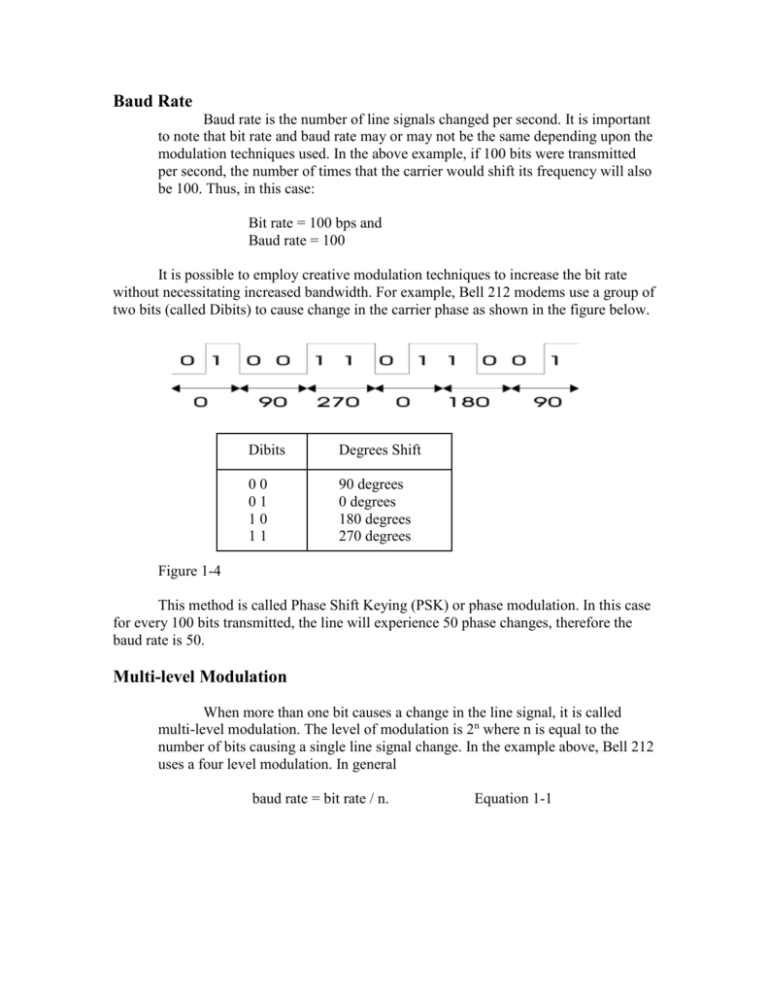
Baud Rate Baud rate is the number of line signals changed per second. It is important to note that bit rate and baud rate may or may not be the same depending upon the modulation techniques used. In the above example, if 100 bits were transmitted per second, the number of times that the carrier would shift its frequency will also be 100. Thus, in this case: Bit rate = 100 bps and Baud rate = 100 It is possible to employ creative modulation techniques to increase the bit rate without necessitating increased bandwidth. For example, Bell 212 modems use a group of two bits (called Dibits) to cause change in the carrier phase as shown in the figure below. Dibits Degrees Shift 00 01 10 11 90 degrees 0 degrees 180 degrees 270 degrees Figure 1-4 This method is called Phase Shift Keying (PSK) or phase modulation. In this case for every 100 bits transmitted, the line will experience 50 phase changes, therefore the baud rate is 50. Multi-level Modulation When more than one bit causes a change in the line signal, it is called multi-level modulation. The level of modulation is 2n where n is equal to the number of bits causing a single line signal change. In the example above, Bell 212 uses a four level modulation. In general baud rate = bit rate / n. Equation 1-1 Example 1.1 A modem uses 3 bits per signal change and is transmitting data at a rate of 2400 bps. Determine: A) it’s baud rate B) the modulation level Solution: A) Baud rate = bit rate / n = 2400 / 3 = 800 baud B) Modulation level = 2n = 23 =8 This system is using an eight level modulation Example 1-2 A modem which is using a 16 level modulation is transmitting at 9600 baud. A) How many bits per signal change is it using? B) Calculate it’s bit rate. Solution: A) Modulation level = 2n 16 = 2n n=4 B) Baud rate = bit rate / n Therefore, bit rate = baud rate X n = 9600 X 4 = 38400 bps Simplex, Half Duplex and Full Duplex Transmission A) Simplex – Transmission in one direction only. Example thermostat to furnace. Thermostat Figure 1-5 Furnace B) Half Duplex (HDX) – Communication in both directions, but only one at a time. Example Intercom system. Transmit Receive Receive Transmit Figure 1-6 C) Full Duplex (FDX) – Communications in both directions simultaneously either on separate pairs of wires or using some kind of modulation. Example, Bell 103 uses FSK to communicate in a FDX mode. See diagram on following page. Transmit Receive Receive Transmit Figure 1-7 Bit Error Rate (BER) Bit error rate is defined as the ratio of erroneous bits received to the number of bits sent. Bit error rate = Be / B Equation 1-2 A typical voice grade channel may generate error rates of 10-5. Block Error Rate (BLER) Block error rate is the ratio of the number of blocks of data with at least one error to the total number of blocks transmitted. BLER = Number of blocks with errors Total number of blocks sent Equation 1-3 Asynchronous Systems Data is transmitted as soon as it is available. Example – a keyboard. When a key is pressed a character is generated and transmitted immediately. The character is enclosed in a frame with one “low” start bit and 1, 1 ½, or 2 “hi” end bits. The receiver looks for the low start bit for the beginning of data. Asynchronous transmission is widely used for low data rates because it is inexpensive and easy to implement. Synchronous Transmission Synchronous transmission refers to sending data at a fixed periodic rate with a synchronization character at the beginning of the message to synchronize the receiver with the transmitter. When no data is being sent a sync character is continuously sent to keep the receiver synchronized with the transmitter. Synchronous systems are complex and are used for higher data rates. Baseband Signals An unmodulated signal is usually called a baseband signal. A baseband signal is used to modulate a carrier. In other words, the information bearing signal in a communications system is called a baseband signal. Keep the following distinctions in mind when dealing with baseband and broadband signals: A) B) C) D) Uses digital signaling Limited Bandwidth Usually unmodulated Usually uses time division multiplexing for channel sharing Broadband Systems A) B) C) D) Uses analog waveforms Has a large bandwidth (MHz to GHz) Uses analog modulation Uses frequency division multiplexing for channel sharing Channel Capacity and Bandwidth Shanon’s Law – Shanon’s law relates channel capacity and bandwidth requirements in a noisy channel. C = BW log2 (1+S/N) C = Channel capacity in bps BW = Bandwidth in hertz S/N = signal to noise ratio Also note that Log2N = (Log 10 N) / Log10N = Log10N / 0.3 Equation 1-4 Example 1-3 A signal is to be transmitted at 19.2 Kbps through a noisy channel whose signal to noise power ratio is 30 dB. A) Calculate the bandwidth required. B) Can this signal be transmitted using a standard telephone channel? Solution: A) C = BW Log2(1+S/N) C = 19.2 Kbps S/N = 30 dB BW = ? First convert S/N ratio into a linear ratio. Power ratio in dB is given by: dB = 10Log(S/N) 30 = 10log(S/N) S/N = Antilog 3 S/N = 1000 C = BW log2(1 + 1000) 19.2 X 1000 = BW log21001 19.2 X 1000 = BW ((Log101001) / (0.3)) BW = 19.2 X 1000 X 0.3 Log101001 BW = 19.2 X 1000 X 0.3 3 BW = 19.2 X 100 BW = 1.92 KHz B) Yes, since the BW requires is 1.92 KHz and the telephone bandwidth is 3 KHz. Example 1-4 Calculate the capacity of a 64 KHz channel whose voltage signal to noise ratio is 25 dB. Solution: C = BW ((log10(1+S/N)) / 0.3) S/N = dB = 20 Log signal voltage noise voltage 25 = 20 LogS/N LogS/N = 1.25 S/N = 17.782 C = 64 X 1000 (1+17.782) 0.3 C = 64 X 1000 X 18.782 3 C = 400.68 Kbps RS – 232 Connector (Refer to attached handouts) EIA (Electronics Industries Association) standard for data communications designed for rates up to 19.2 Kbps. RS stands for Recommended Standards. TTL RS-232 State Logic 0 0VDC +5 to +15 VDC SPACE Logic 1 +5VDC -5 to –15 VDC MARK Secondary channels are used for error detection and correction. The reader of this material is strongly suggested to review the material covered in the Telecom course corresponding to the topics presented in this module before attempting end of module assignment and test.
