Homework 4.10 - Education Scotland
advertisement
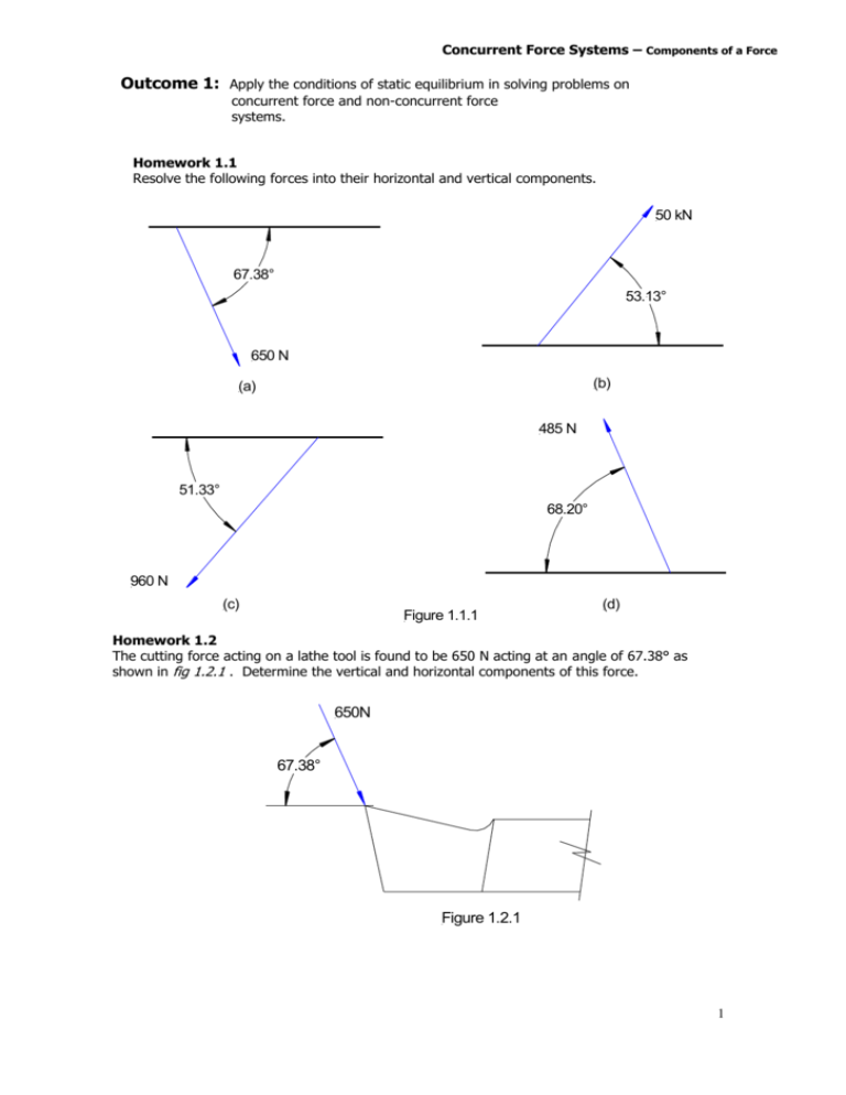
Concurrent Force Systems – Components of a Force Outcome 1: Apply the conditions of static equilibrium in solving problems on concurrent force and non-concurrent force systems. Homework 1.1 Resolve the following forces into their horizontal and vertical components. 50 kN 67.38° 53.13° 650 N (b) (a) 485 N 51.33° 68.20° 960 N (c) Figure 1.1.1 (d) Homework 1.2 The cutting force acting on a lathe tool is found to be 650 N acting at an angle of 67.38° as shown in fig 1.2.1 . Determine the vertical and horizontal components of this force. 650N 67.38° Figure 1.2.1 1 Concurrent Force Systems – Resultant and Equilibrant Home work 1.3 A boat is being towed into a dry-dock by means of a rope attached as shown in fig. 1.3.1 . If the force in the rope is 400 N when it makes an angle of 28° to the centre line of the boat. Calculate the components of the force pulling it forward and towards the side of the deck. Dry Dock 28° Figure 1.3.1 400N Homework 1.4 Calculate the RESULTANT of each of the force systems shown below. Copy each diagram and illustrate the RESULTANT and the EQUILIBRANT on the diagrams. 30 N 10 N (a) 40 N (b) 60° 30 16 N 45° 45° (c) 15 N 20 N 45 N 45 N 30 N (d) 60° 60° 20 N (f) (e) 45 N 30 N figure 1.4.1 2000 N (tight side) Belt 10° (f) Calculate the resultant force on the roller below in fig.1.4.2. (slack side) P Rope figure 1.4.3 (g) 20° Roller 160 N figure 1.4.2 Pulley Calculate the resultant force acting on the bearing resulting from the belt shown in fig.1.4.3. 2 Concurrent Force Systems – Resultant and Equilibrant (h) fig. 1.4.4 Shows the Vertical force 600 N and horizontal force 250 N acting on a lathe tool point. Calculate the resultant force and its angle to the horizontal. 600N 90° 250N figure 1.4.4 Homework 1.5 Calculate the resultant of the force systems shown in figure 1.5.1 & 1.5.2 and illustrate them on a diagram showing the equilibrant. 20N (b) (a) 10N 20° 12N 60° 12N 45° 30° 40° 8N 15N 16N 10N Figure 1.5.2 Figure 1.5.1 150 kN (c) Calculate the resultant force on the gusset plate shown in figure 40 kN 100 kN 1.5.3 80 kN Gusset Plate 250 N Link ° 10° Figure 1.5.3 figure 1.5.4 250 N Pulley (d) Calculate The force in the link shown in figure 1.5.4 and the angle it makes with the horizontal. 3 Non-Concurrent Force Systems – Resultant and Equilibrant Homework 1.6 The lever A, B, C, D is in equilibrium under the action of the forces shown figure 1.6.1. Determine; (a) the distance ‘x’ from B to the point of application of the 60 N force (b) the reaction at the pivot. 60 N D 100 N 0.2 m x 60° 130 N A C B 0.6 m 0.2 m Figure 1.6.1 Homework 1.7 The lever A, B, C, D, E is in equilibrium under the action of the force system shown in figure 1.7.1. Determine; (a) the magnitude of force P. (b) the magnitude and direction of the reactions on the lever at pivot D. 100 mm 100 mm 300 mm 100 mm E 100 N D C 70° A B 200 N 120° Figure 1.7.1 P Homework 1.8 Figure 1.8.1 shows the tension in the tight and slack side of a crossed belt drive passing round a pulley of weights, 400 N. Calculate the resultant force at the shaft and the direction in which it acts. 30° 5000 N 1000 N 1m A 60 ° B B figure 1.8.1 1000 N 1000 N Shaft 1m 400 N Homework 1.9 The frame shown is in equilibrium under the action of the two 1000 N forces and forces at A and B. The force at B acts in the direction shown. Calculate; (a) the magnitude of force at B. (b) the magnitude and direction of the force at A. 4 Non-Concurrent Force Systems – Resultant and Equilibrant Homework 1.10 The lever shown in fig.1.10.1 is in equilibrium. Determine the force F and the direction and magnitude of the force at fulcrum A. 0.4 m F 0.2 m 1 kN A m ru c l Fu 20 N 0.4 m 4 kN A 200 10 00 Figure 1.10.1 Homework 1.11 For the brake mechanism shown , pivot points are C, E and H and members are pin jointed at B, D, F, G, and J. (a) For an effort of 20 N applied at A, determine the nature and magnitude of the force in rod J, K. (b) Determine the magnitude and direction of the reactions at the pivots C and E. E 200 C G F 300 B 500 D J H 350 K Figure 1.11.1 200 mm 400 mm Homework 1.12 For the lever shown in fig. 1.12.1. Determine the magnitude and direction of the forces acting at B and C. 250 mm B C ° 60 15 kN Figure 1.12.1 D 45° A 90 kN 5 Framed Structures – Nodal Analysis Outcome 2: Apply the conditions of static equilibrium in solving problems on Simple structural systems. C B Homework 2.1 The pin jointed frame figure 2.1.1 carries a vertical load of 1000 kN as shown. Given the load in member BC is 1155 kN: Tie. 60° (a) Write down the reaction at B. (b) Calculate the reaction at A. (c) Determine using nodal analysis the force in members AC, CD and AD. 60° A D . Figure 2.1.1 1000 kN 30° 100 kN . A Homework 2.2 (a) Calculate the reaction at supports B and C of the framework shown. (b) Calculate the load in each member of C the loaded frame. 30° 60° B Figure 2.2.1 100 kN B 60 kN . . C . Homework 2.3 For the symmetrical frame shown calculate the force in members BC, CE and ED in figure 2.3.1. A 60° 60° 60° 60° D E Figure 2.3.1 6 Framed Structures – Nodal Analysis B 30° D A F C 30° Homework 2.4 Calculate the force in each member of the lifting arrangement shown in figure 2.4.1. 1000 kN 30° E Figure 2.4.1 B A Homework 2.5 Determine the loading in each member of the lifting frame shown in figure 2.5.1. 40 kN 45° D 30° C Figure 2.5.1 C 'x' B 45° 40 kN 45° A Homework 2.6 A wire rope attached to the wall at ‘x’ passes around a pulley held on a frame as shown. In figure 2.6.1 the rope carries a vertical load of 40 kN. Determine the load in each member of the frame. Figure 2.6.1 7 Framed Structures – Nodal Analysis B A Homework 2.7 C 30° Determine the load in each member of the framework shown in figure 2.7.1 30° D Figure 2.7.1 10 kN Homework 2.8 C B An overhead conveyor track is supported by a series of pin jointed frames shown in figure 2.8.1 . The maximum load including the cage running on the track is 20 kN. 30° 30° A D E Determine; 20 kN (a) the reaction at supports A and D Figure and 2.8.1nature of (b) by using nodal analysis the magnitude the forces in the members DE, DC, EC and CB. C B D E Homework 2.9 (1) 45° 45° 45° F A H G (a) (b) (2) Determine the most highly loaded member in the pin jointed frame shown in figure 2.9.1. in tension. in compression. Identify the redundant member(s). Figure 2.9.1 100 kN 8 Framed Structures – Nodal Analysis Homework 2.10 Determine the load in the members of the framework shown in figure 2.10.1 30 ° 5 kN 45° 4 kN 30° figure 2.10.1 9 Properties of Materials– Stress, Strain and Youngs modulus Outcome 3: Use and interpret data from a tensile test in studying properties of materials. Homework 3.1 A wire 5 mm in diameter is subjected to a pull of 200 N. Calculate the tensile stress in the wire. Homework 3.2 A mass of 1.1 Tonne is suspended at the end of a vertical bar, the cross-section of which is 75 mm X 50 mm. Calculate the tensile stress in the bar. Homework 3.3 A round bar of mild steel 40 mm in diameter carries a compressive force of 6800 N. Find the compressive stress in the bar. Homework 3.4 A piece of square steel bar 32 mm X 32 mm is held in a vice which exerts a force of 5000 N. Find the compressive stress in the bar. Homework 3.5 The tensile stress set up in a suspension rod when carrying a load of 2 kN is 113 N/mm². What will be the dimension of the cross-section if, (a) the rod is circular and (b) if the rod is square. Homework 3.6 A steel support 25 mm diameter carries a compressive load which sets up a stress of 81.5 N/mm² in the support. Calculate the magnitude of the load. Homework 3.7 A Tow wire 3 metres long stretches 0.0223 mm when pulling a load. Calculate the strain in the wire and express this as percentage strain. Homework 3.8 Calculate the compressive strain in a steel component 150mm long , if the force causes it to shorten by 0.05mm. Express your answer as percentage strain. Homework 3.9 Calculate the extension of a rod 2m long when the percentage strain is 0.05%. Homework 3.10 A supporting column is subjected to a percentage strain of 0.03% and shortens by 0.9mm. Calculate the original length of the column Homework 3.11 A steel bar 4 metres long has a diameter of 36 mm and carries a force of 9850 N. Find the extension if Youngs Modulus for the material is 198 GN/m². Homework 3.12 A bar of mild steel 35 mm in diameter is subjected to a compressive force of 15000N. What is reduction in length if the bar is 200mm long, take E = 198 GN/m². Homework 3.13 A length of wire 2 metres long and of diameter 0.4mm stretches 8mm when a force of 60 N is applied. Calculate:(a) The stress in the wire. (b) The strain as a percentage. (c) The value of Young’s modulus for the material. 10 Properties of Materials– Stress, Strain and Youngs modulus Homework 3.14 A wire 0.75 mm in diameter and 2.65 metres in length is stretched 0.0027 m by a force of 85 N. Find the value of Young’s modulus for the material. Homework 3.15 A link in a machine mechanism is made from steel with a value of E = 210 kN/mm² and has dimensions of 20mm diameter X 400 mm long. During operation the link is alternatly subjected to a tensile force of 4.4 kN and a compressive force of 1.1 kN. Calculate the total change in length of the link during one cycle of operation. Homework 3.16 A tie-bar of rectangular section 70 mm X 15 mm streches 0.15 mm over a length of 210 mm when loaded. What is the load carried by the tie-bar. E = 210 kN/mm². Homework 3.17 A mild steel tube 50 mm outside diameter, 25 mm inside diameter and 200 mm long is held vertically in a press which exerts a force of 50 kN. Calculate the stress in the material and the decrease in length. The value of E = 210 kN/mm². Homework 3.18 During a tensile test on a metal specimen 50 mm long and cross-section area 100mm² a point on the straight line portion of the graph below the limit of proportionality was recorded as force 46 kN and corresponding extension 0.089 mm. From the information given calculate the value of the modulus of elasticity E for the material. Homework 3.19 (a) The stress/strain graphs in figure 3.19.1, which are all drawn to the same scale, were obtained from tensile tests carried out on identically sized specimens of 4 different materials. Stress (N/mm2) 600 500 400 300 B D C 200 A 100 0.1 0.3 0.2 0.4 0.5 0.6 Strain figure 3.19.1 Using the graphs, indicate which of the four material is; (i) the strongest; (ii) the most ductile. (iii) the most brittle (iv) the ‘stiffest’ (highest value of ‘E’) (b) select a material which; 11 Properties of Materials– Stress, Strain and Youngs modulus (i) (ii) (iii) is suitable to make bolts and screws; is most suitable for drawing into wires; the least suitable for resisting bending. Homework 3.20 (a) Sketch a typical stress/strain graph in good proportion for a mild steel specimen which has a yield point stress of 325 N/mm² and ultimate strength of 500 N/mm². Indicate these points clearly on the graph. On the same graph indicate and name 2 other significant points. (a) During testing the material displays two distinct types of behaviours, elastic deformation and plastic deformation. Indicate these areas on your graph. What information does the extent of the plastic region tell us about the properties of the material. (b) On the same diagram sketch the graph for grey cast iron which has yield point stress of 250 N/mm² and an ultimate strength of 250 N/mm². Show the graphs in the correct relative proportions given that the value of Young’s Modulus of Elasticity for steel is 210 GN/m² and for grey cast iron is 110 GN/m². Homework 3.21 A hollow square-section column which is 1 m x 1 m (outside size) has a wall thickness of 120 mm. Find the maximum load the column can carry if the direct stress is not to exceed 50 N/mm². If the column is made from cast iron and is 1.5 m high calculate the decrease in length when loaded. 12 Properties of Materials– Stress, Strain, Youngs modulusand Factor of Safety Outcome 4: Produce a specification for a structural component. Homework 4.1 A tie rod carries a tensile load of 150 kN and is made from mild steel. (a) Calculate the cross-sectional area of the rod and hence the diameter if the design factor of safety is 3 based on the UTS of the material. (b) What would be the consequences of not using a factor of safety in the design process. Homework 4.2 A tie-rod for a roof truss is 2.5 m long and carries a load of 8 kN. If the factor of safety is 5, determine the cross-sectional area of the tie-rod. What size of square section rod would be suitable. Determine the extension of the tie-rod under this loading condition. Homework 4.3 A cylinder head bolt on an engine is made from high tensile steel with a UTS of 1900 N/mm². The bolt is 10 mm dia. X180 mm long and operates at a Factor of Safety of 6 based on the UTS. If the bolt is tightened to its maximum permissable working stress, calculate; (a) the tensile load (force) in the bolt. (b) the elongation of the bolt when fully tightened. Homework 4.4 A hollow mild steel column is 2.5 m long, 300 mm outside diameter with a wall thickness of 20 mm is subjected to an axial compressive load. The column operates at a safety factor of 2.5 based on the U.T.S. Calculate (i) the maximum permissable load it can carry and, (ii) the amount of contraction at this load. Homework 4.5 A strut 150 mm long is made of a mild steel tube 75 mm external diameter, 50 mm internal diameter with a bronze tube 50 mm external and 25 internal diameter inserted inside it. When loaded the strut is reduced in length by 0.1 mm. Calculate; (i) the total load carried by the strut at this loading. (ii) the factor of safety each material is operating at based on the U.T.S of each material. Bronze Steel m 5m 7 ø 150 mm m ø 50 m ø 25 m m PLAN 13 Properties of Materials– Stress, Strain, Youngs modulusand Factor of Safety Homework 4.6 A mild steel support of section shown has a load of 240 kN applied as shown. Calculate; (i) the total compression of the support due to the load. 10 mm 240 kN 360 mm 240 mm 40 mm 20 mm Figure 4.6.1 what factor of safety is this component operating at (based on the U.T.S) – remember there is two different cross-sections. Homework 4.7 A mild steel tie rod, 6 m long, having a section as shown in figure 4.7.1, is subjected to a tensile load of 150 kN. Determine; the tensile stress in the rod; (b) the elongation of the rod. (c) the factor of safety at this load. 12 mm 75 mm (a) 76 mm Homework 4.8 A round stepped bar has both sections of equal length, see figure 4.8.1. 'L' 12 mm (ii) 'L' diameter 'D' Extension 0.3 mm Diameter 'd' Extension 0.5 mm Figure 4.8.1 When loaded in tension with force F as shown the measured elongation of each section is 0.3 mm and 0.5 mm respectively. Calculate the ratio of the diameters. Homework 4.9 The ram in a hydraulic jack is a titanium alloy tube, having an external diameter equal to 1.5 times its inside diameter. It is designed to support a load of 500 kN operating at a factor of safety of 5. Determine the internal and external diameters of the tube. 14 Properties of Materials– Stress, Strain, Youngs modulusand Factor of Safety Homework 4.10 (i) Explain what is meant by the terms listed below as they apply to engineering materials and testing, stating the units as appropriate. Use diagrams to illustrate your answers. (ii) (a) (b) (c) (d) (e) (f) (g) (h) (i) Stress or intensity of stress ‘σ’. Strain ‘Є’ and percentage strain. Young’s Modulus of Elasticity ‘E’. Yield point and yield stress. Limit of proportionality. Ultimate load and ultimate stress (strength). Load at fracture. Factor of Safety based on U.T.S and factor of Safety based on the yield stress. Plastic and elastic deformation. (a) An engine bolt of mild steel diameter 10mm X 80mm long operates with a maximum allowable stress of 200 N/mm². What is the maximum tensile load that may be applied to the bolt. (b) (c) Determine the strain in the bolt and the increase in length. What effect would selecting a “high tensile” steel with larger value of Young’s Modulus have on the “performance” of the bolt. What is the factor of safety used in this bolt design. (i) based on the U.T.S. (ii) based on the yield stress. Why is the method in (ii) often preferred. Sketch a typical stress/strain graph, in good proportion, for mild steel having the property values used in (a) above and show on the diagram the maximum allowable working stress given in (a) above. (d) (e) (f) (using information from the data booklet) Homework 4.11 In a tensile test to destruction on an alluminium alloy specimen, diameter 11.283mm and gauge length 50mm the following results were obtained. Force kN Extension mm 0 0 2 4 6 8 10 12 14 16 18 19 20 24 28 29 28 0.0133 0.0266 0.04 0.0532 0.067 0.08 0.093 0.1064 0.15 0.234 0.5 1.3 3.4 4.4 8.4 The maximum force recorded was 29.6 kN and the force at fracture was 24 kN. The total extension was 10.5mm. (a) Construct a table showing the stress/strain values similar to the table above and use this to plot a stress/strain graph for the specimen. Vertical scale stress 1cm rep. 40 N/mm² Horizontal scale strain 1cm rep. 0.02 units [Note:- using this scale it will not be possible to accurately plot the first 8 points] Estimate from this graph the Ultimate Tensile Strength of the material. (b) Construct another graph using the same vertical scale for stress, 1 cm rep. 40 N/mm² and a horizontal scale for strain of 1 cm rep. 0.0005 units and from this graph determine; (i) The value of Young’s Modulus ‘E’ of the material. (ii) The limit of proportionality stress. Homework 4.12 15 Properties of Materials– Stress, Strain, Youngs modulusand Factor of Safety A stainless steel suspension wire 25 mm diameter has an ultimate tensile strength 1250 N/m². If the factor of safety is 5, calculate the allowable pull on the wire and find the corresponding elongation on a 36 metre span. E = 207 GN/m². Homework 4.13 A mild steel tension member in a roof truss is subjected to a load of 117 kN. When a factor of safety of 5 is used, find the diameter of the member. If the member is 2 metres long and stretches 0.85 mm under the above force, what is the modulus of elasticity of the steel? 16

