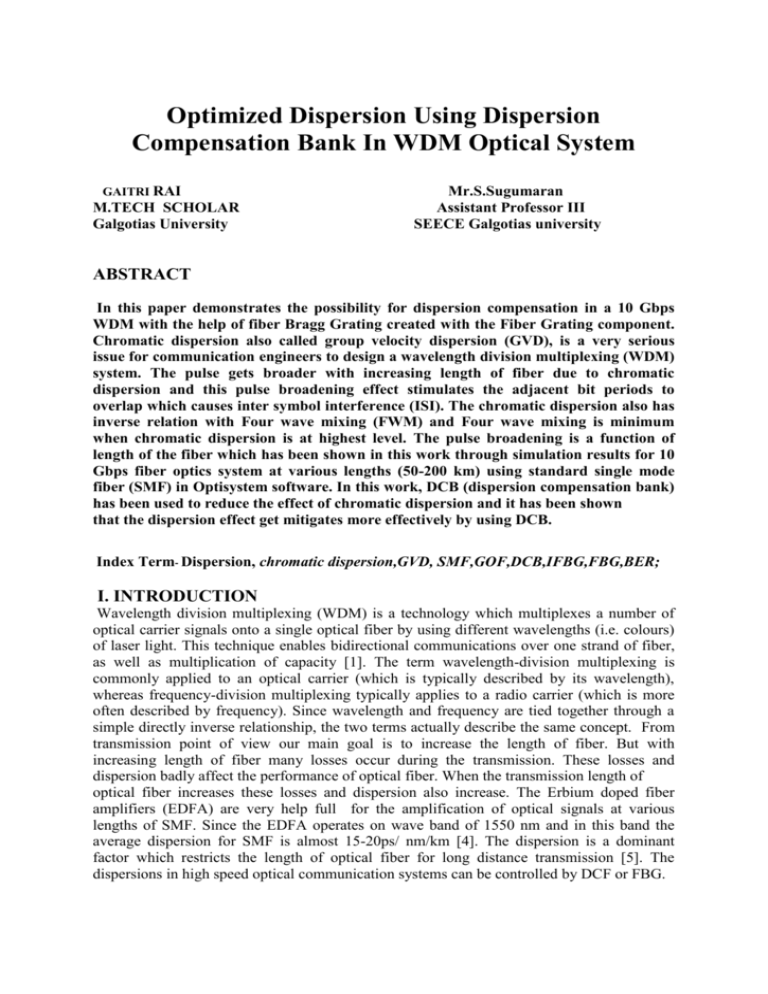
EYE Pattern of WDM system using DCB at 200km SMF
advertisement

Optimized Dispersion Using Dispersion Compensation Bank In WDM Optical System GAITRI RAI M.TECH SCHOLAR Galgotias University Mr.S.Sugumaran Assistant Professor III SEECE Galgotias university ABSTRACT In this paper demonstrates the possibility for dispersion compensation in a 10 Gbps WDM with the help of fiber Bragg Grating created with the Fiber Grating component. Chromatic dispersion also called group velocity dispersion (GVD), is a very serious issue for communication engineers to design a wavelength division multiplexing (WDM) system. The pulse gets broader with increasing length of fiber due to chromatic dispersion and this pulse broadening effect stimulates the adjacent bit periods to overlap which causes inter symbol interference (ISI). The chromatic dispersion also has inverse relation with Four wave mixing (FWM) and Four wave mixing is minimum when chromatic dispersion is at highest level. The pulse broadening is a function of length of the fiber which has been shown in this work through simulation results for 10 Gbps fiber optics system at various lengths (50-200 km) using standard single mode fiber (SMF) in Optisystem software. In this work, DCB (dispersion compensation bank) has been used to reduce the effect of chromatic dispersion and it has been shown that the dispersion effect get mitigates more effectively by using DCB. Index Term- Dispersion, chromatic dispersion,GVD, SMF,GOF,DCB,IFBG,FBG,BER; I. INTRODUCTION Wavelength division multiplexing (WDM) is a technology which multiplexes a number of optical carrier signals onto a single optical fiber by using different wavelengths (i.e. colours) of laser light. This technique enables bidirectional communications over one strand of fiber, as well as multiplication of capacity [1]. The term wavelength-division multiplexing is commonly applied to an optical carrier (which is typically described by its wavelength), whereas frequency-division multiplexing typically applies to a radio carrier (which is more often described by frequency). Since wavelength and frequency are tied together through a simple directly inverse relationship, the two terms actually describe the same concept. From transmission point of view our main goal is to increase the length of fiber. But with increasing length of fiber many losses occur during the transmission. These losses and dispersion badly affect the performance of optical fiber. When the transmission length of optical fiber increases these losses and dispersion also increase. The Erbium doped fiber amplifiers (EDFA) are very help full for the amplification of optical signals at various lengths of SMF. Since the EDFA operates on wave band of 1550 nm and in this band the average dispersion for SMF is almost 15-20ps/ nm/km [4]. The dispersion is a dominant factor which restricts the length of optical fiber for long distance transmission [5]. The dispersions in high speed optical communication systems can be controlled by DCF or FBG. II. DESCRIPTION OF THE OPTICAL DESIGN In this optical design, 4-channel transmits 10Gb/s, is simulated with variety of extinction ratio and fiber lengths. The design consists of 4 transmitters and 4 receivers. In the transmitter side, return to zero (RZ) pulse generator is used in order to generate pseudorandom bit sequence (PRBS). Then, Mach-Zehnder is used to modulate the electric signal from NRZ with continuous wave (CW) laser. An optical fiber with different distances are used to link between the transmitter and the receiver by using an EDFA and DCB for long distances. In the receiver side, Avalanche photodetectors (APDs) are used to convert the received optical signals to electrical signals are filtered through a low pass Bessel filter. Bit Error Rate (BER) analyzers are used to realize the quality of the output signal for each channel. A schematic design of four channels WDM is presented. In this scheme various dispersion compensation components and optical filters are used to compensate the effect of chromatic dispersion. The implementation is shown in figure. Figure:Block diagram DCB (dispersion compensation bank) consist of either three or two dispersion compensation components. The ideal fiber Bragg grating (IFBG) Fiber Bragg grating (FBG) Gaussian optical filter (GOF) Figure2:DCB System DCB is just like fiber segment having attributes of two dispersion compensation components in a single package.DCB is a combination of FBG or IFBG and GOF available in single package .The Grating is just like a dielectric mirror which reflects back particular wavelengths and passes all other wavelengths. The grating is used in small segment of fiber and it is obtained by making gradual variations in the core of fiber. In this system, we have used the ideal dispersion compensation grating and FBG, operating at frequency of 193.1 THz with Effective index of 1.45 . In this scheme, we also used GOF (Gaussian optical filter) to make the response of Ideal FBG more flat and smooth, because GOF has property to minimize the rise and fall time and minimizing group delay which is very helpful to reduce the effect of chromatic dispersion. GOF which has been used here is operating at frequency of 193.1 THz and bandwidth of 10 GHz. The EDFA is most important component in fiber optics communication systems and it can efficiently amplify the wavelength in region of 1.5µm. III. SIMULATION DESIGN The simulation is performed by the use of Optisystem software. Optisystem13 gives the ability to the designer to change the design and the parameters to get better results. As shown in figure 2 the transmitter side consists of 4 transmitters at 193.1, 193.2, 193.3, and 193.4 THz with almost 100GHz spacing between the channels. Then, the media is WDM MUX, optical fiber with different lengths, EDFA, DCB and WDM DEMUX. In the receiver side, photodetector APDs, low pass Bessel filters and BER analyzers. The total accumulated dispersion of the SMF is 16x80 = 1280 ps/nm. We swept the total dispersion of FBG from 30 to -3000 ps/nm. The bit rate is set to 10 Gbps. WDM network consist an optical span which has a loop control. This loop control can be used to run the transmission of signal one or more time in optical fiber. In this simulation, we want to investigate the dispersion-limited performance of the system. The designed system is shown in Figure 3. Figure 3: WDM system topology with DCB at 8o km SMF IV RESULTS AND DISCUSSION Eye diagram or also known as eye pattern in telecommunication is an old technique used in order to evaluate the received signal. Totally opened eye pattern represents the lowest level of distortion. BER analyzers create eye diagrams by making a pseudorandom arrangement of 1s and 0s in a symmetric rate but in an arbitrary manner. In Optisystem, eye diagram, which can be found in the BER analyzer show various traces of modulated signal in order to create an eye diagram. Because of the shape of the pattern that looks as if it is an eye, it is called an eye diagram. We can analyze different parameters like Q factor, Min BER, and BER pattern. In this simulation Q factor is better as shown Figure 4: graph for Quality factor Figure 5: Graph for Min BER Figure 6: Graph for Threshold Figure 8:Optical spectrum after WDM Figure 10: Graph for BER pattern . Figure 7: Graph for Height Figure 9:. Optical spectrum at receiving end Figure 11: Eye diagram COMPARISION OF WDM SYSTEM WITH OR WITHOUT DCB AT 80KM SMF In this system, we have used the ideal dispersion fibre bragg grating and operating at frequency of 193.1 THz with effective index of 1.45 and length of 2mm. the signal is original signal with an 80 Km long optical fiber cable is used as transmission medium Figure 12:EYE Pattern without DCB Figure 13:EYE Pattern with DCB In this simulation we are observing that the Q factor without DCB is 22.3677 which is increased to 23.3415.Min BER without DCB is 2.4454e-094 which is improved 5.12435e121.EYE height without DCB is .21008 and after DCB it is .211907.Threshold without DCB is .0139233 and after implementing DCB we get .0137181 which is reduced in a very less amount. BER ANALYSIS AT VARIOUS LENGHTS Now we move towards the analysis of dispersion at various lengths of single mode fiber and we have used the ideal dispersion fiber bragg grating and operating at frequency of 193.1 THz with effective index of 1.45 and length of 2mm and GOF as a DCB(dispersion compensation bank) . We have used BER analyzer to analyze the effect various lengths on BER, maximum Quality factor etc at 20dB power level. The signal is transmitted on SMF at various lengths. 1. At fiber length of 50 km. Figure 14: EYE Pattern of WDM system using DCB at 50km SMF In this simulation we are observing that the Q factor is23.6626,Min BER 2.49579e-124,EYE height .840911,Threshold .0344497.Q factors is highest than DCB AT 80,100 ,200km SMF and without DCB at 80km SMF.OSNR is also improved. Noise is also reduced. EYE height maximum, so dispersion is less. 2. At fiber length of 100 km Figure 15: EYE Pattern of WDM system using DCB at 100km SMF In this simulation we are observing that the Q factor is20.6256, Min BER 4.90473e-095, EYE height .0827458, Threshold .00581346.Q factors is decreased than DCB AT 50,80 kms SMF and without DCB at 80km SMF.OSNR is also reduced . EYE height is less that all other method except 200km SMF, so dispersion is less than 200km WDM system with DCB. 3. At fiber length of 200 km Figure 16: EYE Pattern of WDM system using DCB at 200km SMF In this simulation we are observing that the Q factor is 7.87062, Min BER 9.40547e-016,EYE height .048016,Threshold .00114661.Q factors is decreased than DCB AT 50,80,100 kms SMF and without DCB at 80km SMF.OSNR is also reduced. EYE height is also reduced. Threshold is also minimum in this case. It means that overall quality of system decreases by increasing the length of the fibre, so dispersion is also increased in this system. CONCLUSION This paper briefly presents the analysis of chromatic dispersion at various lengths (50 km, 100 km & 200 km) of SMF for 10 Gbps fiber optics communication system. The analysis is done on the basis of simulation results obtained from Optisystem software. Then a dispersion compensation technique using DCB (dispersion compensation bank) is briefly discussed in this paper and it has been shown that the dispersion effect get mitigates more effectively by using DCB by using BER analyzer eye diagram to analyze the BER and maximum Q. factor etc; also it has been shown that BER decreases by increasing lengths at the same input power. we can conclude that chromatic dispersion effect can be mitigated using DCB by inducing the attributes of IFBG or FBG and GOF in an appropriate proportion in the same segment of single mode fiber. So instead of using IFBG or FBG and GOF separately, we can use DCB which is more efficient to mitigate the effect of chromatic dispersion in SMF having 10 Gbps data rate DCB is also cost effective because it has the attributes of two dispersion compensation components in a single package. The idea of DCB is presented for first time in this work and DCB will be very helpful to compensate the effect of chromatic dispersion in future. REFERENCES [1]Govind P. Agrawal, Fiber-Optic Communication Systems, third edition. [2]Gerd Keiser, OPTICAL FIBER COMMUNICTION, 2013th ed. New Delhi, India: McGraw Hill Education. [3]Amandeep Kaur, “Polarization Mode Dispersion compensation in WDM system using dispersion compensating fibre” International Journal of Engineering Research and Applications (IJERA) ISSN: 2248-9622 www.ijera.com Vol. 2, Issue 2,Mar-Apr 2012, pp.668-673 [4] Mohammad. Amin Dallali "Malin Premaratne Power and dispersion constrained optimization of optical links with unequally spaced repeater modules" Optical Fiber Technology,Vol No.13, pp. 309-317, October 2007. [5] Zou X Y, Hayee M I, H wang S M, Willner A.E. “Limitations in 10Gb/s WDM opticalfiber transmission when using a variety of fiber types to manage dispersion and nonlinearities”, Journal of Lightwave Tech.,vol:14.No.6, pp. 1144-1152, June,1996. [6] R J Nuyts, Y K Park, and P Gallion“Performance improvement of 10 Gbps standard fiber transmission system by using the SPM effect in the dispersion compensating fiber,” IEEE Photonics Technology Letter, vol No 8, pp. 1406–1408, 1996. [7] M J Cole, H Geiger, R I Laming, S Y Set, M N Zervas, W H Loh, Gusmeroli“Broadband dispersion-compensating chirped fiber Bragg gratings in 10 Gbps NRZ 110 km nondispersion-shifted fiber link operating at 1.55 �m ”Electronics Lett., vol No.33, pp.70 71, 1997. [8] John M. Senior, “optical fiber communications Principle and practice”, second edition, prentice hall of India.


