Tutorial 1 - UniMAP Portal
advertisement
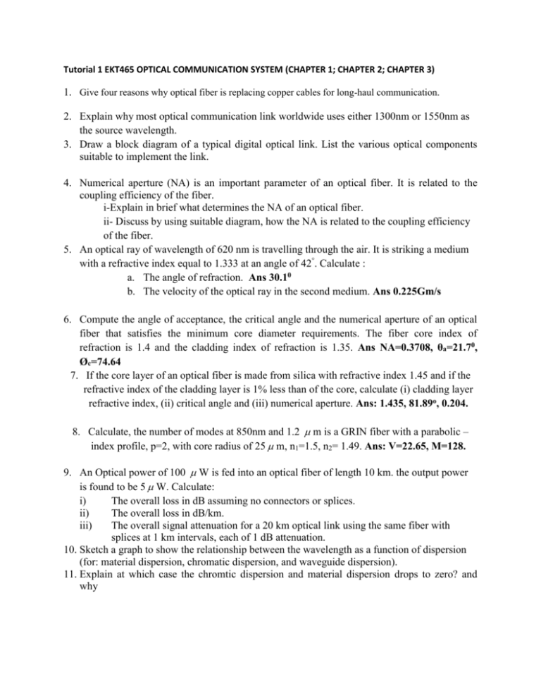
Tutorial 1 EKT465 OPTICAL COMMUNICATION SYSTEM (CHAPTER 1; CHAPTER 2; CHAPTER 3) 1. Give four reasons why optical fiber is replacing copper cables for long-haul communication. 2. Explain why most optical communication link worldwide uses either 1300nm or 1550nm as the source wavelength. 3. Draw a block diagram of a typical digital optical link. List the various optical components suitable to implement the link. 4. Numerical aperture (NA) is an important parameter of an optical fiber. It is related to the coupling efficiency of the fiber. i-Explain in brief what determines the NA of an optical fiber. ii- Discuss by using suitable diagram, how the NA is related to the coupling efficiency of the fiber. 5. An optical ray of wavelength of 620 nm is travelling through the air. It is striking a medium with a refractive index equal to 1.333 at an angle of 42°. Calculate : a. The angle of refraction. Ans 30.10 b. The velocity of the optical ray in the second medium. Ans 0.225Gm/s 6. Compute the angle of acceptance, the critical angle and the numerical aperture of an optical fiber that satisfies the minimum core diameter requirements. The fiber core index of refraction is 1.4 and the cladding index of refraction is 1.35. Ans NA=0.3708, θa=21.70, Øc=74.64 7. If the core layer of an optical fiber is made from silica with refractive index 1.45 and if the refractive index of the cladding layer is 1% less than of the core, calculate (i) cladding layer refractive index, (ii) critical angle and (iii) numerical aperture. Ans: 1.435, 81.89o, 0.204. 8. Calculate, the number of modes at 850nm and 1.2 m is a GRIN fiber with a parabolic – index profile, p=2, with core radius of 25 m, n1=1.5, n2= 1.49. Ans: V=22.65, M=128. 9. An Optical power of 100 W is fed into an optical fiber of length 10 km. the output power is found to be 5 W. Calculate: i) The overall loss in dB assuming no connectors or splices. ii) The overall loss in dB/km. iii) The overall signal attenuation for a 20 km optical link using the same fiber with splices at 1 km intervals, each of 1 dB attenuation. 10. Sketch a graph to show the relationship between the wavelength as a function of dispersion (for: material dispersion, chromatic dispersion, and waveguide dispersion). 11. Explain at which case the chromtic dispersion and material dispersion drops to zero? and why 12. Explain why profile dispersion is more significant in multimode fibers that in single-mode fibers? 13. Sketch a graph to show the relationship between the wavelength as a function of dispersion (for: material dispersion, chromatic dispersion, and waveguide dispersion). 14. Sketch and illustrate in brief the spectral variation of propagating attenuation, describe the major mechanisms for attenuation and identify the wavelength for optimum performance. 15. Four ports directional coupler has 4:1 splitting ratio and an excess loss equal to 2 dB. The coupler’s directionality is 40 dB. a. What fraction of the input power goes to each of the ports? Ans P0/P1= 1.9811, P0/P2=7.924, P0/P3=1x10-4 b. Compute the throughput loss and the tap loss? Ans Throughput = 2.969dB, Tap=8.989dB
