26 50 00 Lighting
advertisement
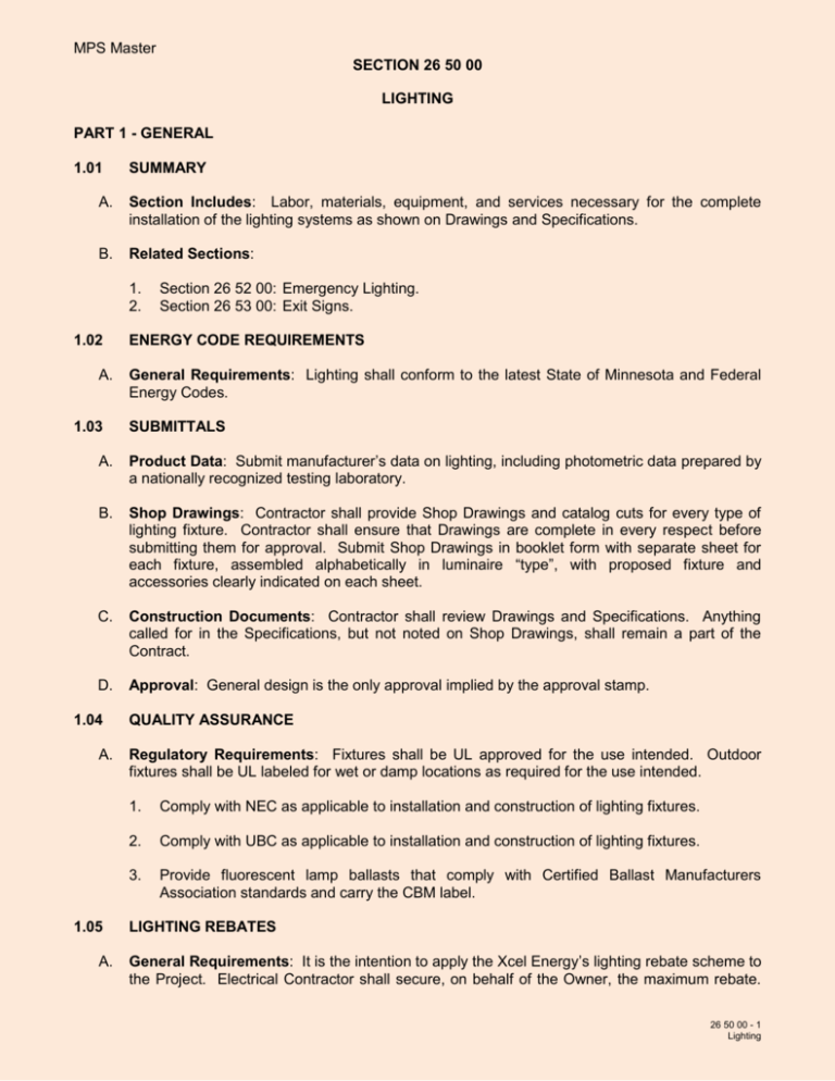
MPS Master SECTION 26 50 00 LIGHTING PART 1 - GENERAL 1.01 SUMMARY A. Section Includes: Labor, materials, equipment, and services necessary for the complete installation of the lighting systems as shown on Drawings and Specifications. B. Related Sections: 1. 2. 1.02 A. 1.03 Section 26 52 00: Emergency Lighting. Section 26 53 00: Exit Signs. ENERGY CODE REQUIREMENTS General Requirements: Lighting shall conform to the latest State of Minnesota and Federal Energy Codes. SUBMITTALS A. Product Data: Submit manufacturer’s data on lighting, including photometric data prepared by a nationally recognized testing laboratory. B. Shop Drawings: Contractor shall provide Shop Drawings and catalog cuts for every type of lighting fixture. Contractor shall ensure that Drawings are complete in every respect before submitting them for approval. Submit Shop Drawings in booklet form with separate sheet for each fixture, assembled alphabetically in luminaire “type”, with proposed fixture and accessories clearly indicated on each sheet. C. Construction Documents: Contractor shall review Drawings and Specifications. Anything called for in the Specifications, but not noted on Shop Drawings, shall remain a part of the Contract. D. Approval: General design is the only approval implied by the approval stamp. 1.04 A. 1.05 A. QUALITY ASSURANCE Regulatory Requirements: Fixtures shall be UL approved for the use intended. Outdoor fixtures shall be UL labeled for wet or damp locations as required for the use intended. 1. Comply with NEC as applicable to installation and construction of lighting fixtures. 2. Comply with UBC as applicable to installation and construction of lighting fixtures. 3. Provide fluorescent lamp ballasts that comply with Certified Ballast Manufacturers Association standards and carry the CBM label. LIGHTING REBATES General Requirements: It is the intention to apply the Xcel Energy’s lighting rebate scheme to the Project. Electrical Contractor shall secure, on behalf of the Owner, the maximum rebate. 26 50 00 - 1 Lighting MPS Master SECTION 26 50 00 This shall include all negotiations, providing substantiation where required, and making all necessary arrangements on behalf of the Owner. 1. Contractor shall obtain all appropriate rebate forms from the local electric utility. 2. Contractor shall coordinate with the local electric utility to complete the rebate forms as necessary. 3. Contractor shall submit rebate forms and associated dealer invoices required by the local electrical utility to the Engineer for purposes of final coordination between Owner and the local electric utility. 4. Include a copy with Closeout Documents; refer to Section 26 00 00. 5. The following rebates have been approved for this Project: a. Occupancy Sensors PART 2 - PRODUCTS 2.01 A. MANUFACTURERS Acceptable Manufacturers: 1. Light fixture shall be Columbia, Cree, Gotham, HE Williams, Lithonia, Lusio, or Rab. 2. Fixture lamps shall be furnished and installed by Contractor, and shall be manufactured by General Electric, North American Phillips, or Sylvania. 3. Fluorescent lamps shall be Sylvania, Octron 800 Series, rapid start lamps or Owner approved equal, unless otherwise noted, with minimum 80 CRI, a color temperature of 3,500 degree K, a minimum of 36,000 hours based on 12-hour ’ON‘ cycle, have a low mercury content, and Class P certified. Fluorescent fixtures shall have ballast factor of 90 or higher, with a crest factor of 1.7 or lower, and CBM certified. a. Fluorescent lamp ballasts shall be solid-state electronic of full light output type except where dimming ballasts are noted. Ballasts shall be able to withstand voltage transients in accordance with IEEE C62.41 for normal and common modes. Ballasts shall operate at a frequency of not less than 20KHz, and a current total harmonic distortion less than 15 percent. Ballasts shall have an average maximum input power consumption in accordance with ANSI 82.2 methods as noted below. Ballast shall be compatible for use with energy saving lamps: Lamp Input Watts (1) FO32 37 (2) FO32 62 (3) FO32 90 (4) FO32 114 26 50 00 - 2 Lighting MPS Master SECTION 26 50 00 b. c. d. Ballasts shall be Advance Mark V, Magnatek, Osram, Universal or Valmount. High Intensity Discharge (HID) lamps shall be as scheduled. HID ballasts shall have a power factor of 90 or higher, with a crest factor of 1.7 or lower, and shall be encapsulated with a sound limiting and heat transmitting solid non-melt fill material. Capacitor shall be mounted separately from ballast. Complete assembly of ballast and fixtures shall have an operating sound level by test that will not exceed an NC-45 level curve. Light Emitting Diode (LED) systems shall have a minimum color rendering index (CRI) of 80, color temperature of 4000 degrees K and shall be rated for 70 percent lumen output at 50,000 hours. LED shall be manufactured by Cree, Gotham, Lumtec, Lusio, Phillips, or Rab. B. Exterior Fixtures: Exterior mounted light fixtures shall have cold weather ballasts for operating temperature at minus 30 degrees F. C. Lenses: All lenses for fixtures shall be pure virgin acrylic lenses with minimum thickness of 0.125 inches and a minimum weight density of 8.0 ounce per square foot, unless otherwise noted. PART 3 - EXECUTION 3.01 A. INSTALLATION General Requirements: 1. Manufacturer's labels shall be removed from exterior of fixtures. 2. Fixtures should be installed at a time when the work of other trades in the area is substantially complete to avoid damage or defacement after installation. 3. Fixtures shall not be installed on ceilings until ceiling finishes are complete, except fixtures may be installed on exposed T-bar ceilings after T-bars are installed and before tile installation. 4. Where floodlighting has been indicated, Electrical Contractor shall provide for adjusting units during evening hours to Engineer's satisfaction. 5. Directional fixtures shall be aimed as required by Owner's representative. 6. Electrical Contractor shall coordinate fixture locations with the ceiling installation and shall install fixtures in a uniform pattern to tiles or exposed grids. Fixtures shall be symmetrically spaced with rows in alignment and parallel with the building features. Measurements shall be taken from Architectural Drawings, unless dimensions are indicated on Electrical Drawings. 7. Furnish lighting fixtures complete with auxiliaries required for the proper, safe, and distortion free installation in various ceiling construction in which they appear. Determine ceiling types from Architectural Drawings and provide compatible fixtures. 8. Install lighting fixtures in strict accordance with manufacturer’s recommendations and instructions. 26 50 00 - 3 Lighting MPS Master SECTION 26 50 00 9. Continuous rows of fixtures shall be rigidly aligned for true in-line appearance. 10. Pendant mounted fixtures shall be installed with bottom 80 percent of ceiling height from floor or as otherwise noted on Drawings. In cases where conditions make this impractical, contact Engineer for direction. 11. Fixtures shall be supported independent of ductwork and piping. 12. Whenever a lighting fixture or its hanger canopy is applied to a surface mounted outlet box, a finishing ring shall be used to conceal the outlet box. 13. Make splices in internal wiring with approved insulated ”wire nut“ mechanical connectors, suitable for the temperature and voltage conditions to which they are subjected. 14. Where dual switching of 4-lamp and 3-lamp, 2 by 4 fluorescent fixtures is shown, the inboard lamps shall be wired to (1) ballast and the outboard lamps are wired to a second ballast. All other 3-lamp and 4-lamp fixtures shall have a single ballast in accordance with the Minnesota Energy Code. All 3-lamp fixtures shall be tandem wired in accordance with the Minnesota Energy Code. 15. Use grounding type manufactured fixture whip or flexible conduit for lighting pigtails of no more than 6 feet in length, and use grounding type connectors for installing same. MC cable not allowed. No more than 4 whips from one J-box feeding lights. 16. Clean all lighting fixtures upon completion of installation and provide protection from damage during remainder of construction. 3.02 A. FIXTURE MOUNTING General Requirements: 1. Surface fixtures, other than fluorescent type, shall be securely fastened to outlet box unless otherwise indicated. 2. Recessed fixtures, except units to be laid into an exposed grid type ceiling, shall be supported from building structural members or from concealed steel framing channels 1 1/2 inches or larger. No fixtures shall be supported from ceiling tiles. 3. Individually mounted fluorescent fixtures shall be supported within 12 inches of each end of fixture. 4. Continuous row fluorescent fixtures shall be supported within 12 inches of end of each row and at intervals not to exceed 48 inches along entire row. 5. Chain hung fixtures shall be permitted only where specifically noted on Drawings. Chains shall be spaced the same as supports described under this Section. Chains shall be heavy duty, nickel or cadmium plated, suitable for weight of specific fixture. Jack chain shall not be used. Unless otherwise indicated, chain hung fixtures shall be provided with a grounded receptacle and grounded portable cords and plugs to feed individual units or continuous rows as required. Chain hung fixtures shall be located on site to clear mechanical ducts and equipment. 26 50 00 - 4 Lighting MPS Master SECTION 26 50 00 3.03 A. B. SUPPORTS AND FASTENING For Fixtures Not In Exposed T-Bar Grid Ceilings: Fixture supports, or outlet boxes used to support fixtures, shall be securely fastened to building structural members or to concealed steel ceiling framing channels 1 1/2 inches or larger. Fixture hanging rods shall be of adequate dimensions to support fixture and shall be not less than 3/8- inch diameter. Fixture supports shall be fastened to structure as follows: 1. To concrete with steel expansion anchors set into a minimum of 1 1/2 inches of concrete or with 3/8-inch minimum diameter toggle bolts through concrete. 2. To wood with lag screws, a minimum 1/4-inch diameter entering wood structural members a minimum of 2 inches. 3. To 16 gauge steel channels where used to span building bar joists, structural members or ceiling 1 1/2-inch minimum framing channels. Steel channels shall be Steel City, No. 6029 or equal, subject to compliance with requirements of the Contract Documents, and furnished by Electrical Contractor. For Fixtures In Exposed T-Bar Grid Ceilings: Fixtures shall be supported as follows: 1. Lay-in fixtures shall be supported from structure as required by ceiling system installer. a. 3.04 A. Provide independent supports from building steel or other structural member at all (4) corners of the fixture up to the structure in accordance with UBC Article 47.1813. All lay-in fixtures shall be clipped to tee with (2) tee bar clips per State Building Code. 2. All recessed fixtures in lay-in ceilings shall have manufactured fixture whip or flexible metal conduit connections permitting fixture to be lifted out. Maximum flexible conduit shall not exceed 6 feet. (1) to (4) fixtures may be served by a single common outlet box securely fastened to structure. MC or AC cable not allowed. 3. Provide and install fixture retainers or clips for each fixture. 4. Recessed fixtures not designed to lay-in directly on grids shall be centered on ceiling tiles and independently supported. 5. Surface mounted fixtures shall be centered on T-bar grids and secured to that grid with hanger clamps, clips or other approved fasteners designed for the purpose. Unless otherwise noted, ceiling T-bar grid system shall be supported from the structure by ceiling system installer. 6. Supports shall be 16 gauge steel channel installed by this Contractor to span over top of main T-bar grids. Steel channels shall be Steel City, No. 6029 or equal, subject to compliance with requirements of the Contract Documents. Non-main T-bar grids shall not be used to support steel channels. Unless otherwise noted, ceiling T-bar grid system shall be supported from structure by ceiling system installer. SPECIAL FIXTURE COORDINATION Storage and Mechanical/Electrical Rooms: Contractor shall verify actual fixture locations with Architect. Fixture locations shall be revised as required to clear all equipment, ducts, and 26 50 00 - 5 Lighting MPS Master SECTION 26 50 00 piping. B. 3.05 A. 3.06 A. Gymnasium and Physical Education Areas: Contractor shall verify actual fixture locations with Architect. Fixture locations shall be revised as required to clear all ductwork, basketball backstops, curtains, and ceiling mounted equipment. FIELD QUALITY CONTROL General Requirements: 1. After all lighting fixtures have been installed and circuited, test fixtures to confirm compliance to the design intent. Correct all malfunctions detected and retest. 2. At Substantial Completion, replace all lamps that have failed or are observed to be noticeably dimmed as judged by the Architect or Engineer. Furnish spare lamps amounting to 15 percent (but not less than one lamp in each case) of each type and size lamp used. GROUNDING General Requirements: Provide tight equipment grounding connection for each lighting fixture installation where indicated. END OF SECTION 26 50 00 - 6 Lighting
