ISE312_ChemicalMilling
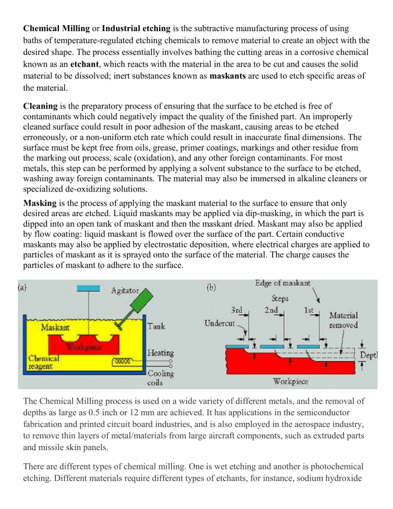
Chemical Milling or Industrial etching is the subtractive manufacturing process of using baths of temperature-regulated etching chemicals to remove material to create an object with the desired shape. The process essentially involves bathing the cutting areas in a corrosive chemical known as an etchant , which reacts with the material in the area to be cut and causes the solid material to be dissolved; inert substances known as maskants are used to etch specific areas of the material.
Cleaning is the preparatory process of ensuring that the surface to be etched is free of contaminants which could negatively impact the quality of the finished part. An improperly cleaned surface could result in poor adhesion of the maskant, causing areas to be etched erroneously, or a non-uniform etch rate which could result in inaccurate final dimensions. The surface must be kept free from oils, grease, primer coatings, markings and other residue from the marking out process, scale (oxidation), and any other foreign contaminants. For most metals, this step can be performed by applying a solvent substance to the surface to be etched, washing away foreign contaminants. The material may also be immersed in alkaline cleaners or specialized de-oxidizing solutions.
Masking is the process of applying the maskant material to the surface to ensure that only desired areas are etched. Liquid maskants may be applied via dip-masking, in which the part is dipped into an open tank of maskant and then the maskant dried. Maskant may also be applied by flow coating: liquid maskant is flowed over the surface of the part. Certain conductive maskants may also be applied by electrostatic deposition, where electrical charges are applied to particles of maskant as it is sprayed onto the surface of the material. The charge causes the particles of maskant to adhere to the surface.
The Chemical Milling process is used on a wide variety of different metals, and the removal of depths as large as 0.5 inch or 12 mm are achieved. It has applications in the semiconductor fabrication and printed circuit board industries, and is also employed in the aerospace industry, to remove thin layers of metal/materials from large aircraft components, such as extruded parts and missile skin panels.
There are different types of chemical milling. One is wet etching and another is photochemical etching. Different materials require different types of etchants, for instance, sodium hydroxide
is used for aluminum, and ferric chloride or ammonia or ammonium persulphate is used for copper. It is widely used to manufacture integrated circuits, and the semiconductor industry uses plasma etching.
Another type is photo chemical milling. This is a process that produces 2D shapes and parts by creating a chemical resist mask on the surface of the sheet metal, and then chemically dissolving material from the unmasked areas.
Photo chemical milling processes are as follows : o A photo resistant coating applied to make the metal sensitive to light o A photo mask is placed over the sensitized sheet metal o The sheet of metal is exposed to ultraviolet light o The photo resist is developed into the masked pattern o The sheet is etched to remove the exposed metal areas leaving the final part o The part is then cleaned
Highest accuracy use photo-resists (semiconductor technology).
(A resist is a substance in which wave energy produces chemical changes making it resistant to acids).
Large Part Example:
Aircraft component (20-mm thickness)
500 x 800 mm 2024-T3 metal alloy plate
Ribbed Pattern is made by removing 80% of the area to a depth of 18mm.
Find time required.
Assume metal removal rate = 0.041 mm/min.
18 mm / 0.041 mm/min. = 439 minutes
Notice: the surface area does not enter into the calculation.
Pg. 2
Electrochemical machining ( ECM ) is a method of removing metal by an electrochemical process. It is normally used for mass production and is used for working extremely “hard” materials or materials that are difficult to machine using conventional methods. Its use is limited to electrically conductive materials. ECM can cut small or odd-shaped angles, intricate contours or cavities in hard metals, such as titanium, high nickel, cobalt, and rhenium alloys. Both external and internal geometries can be machined.
ECM is often characterized as "reverse electroplating," in that it removes material instead of adding it. It is similar in concept to electrical discharge machining (EDM) in that a high current is passed between an electrode and the part, through an electrolytic material removal process having a negatively charged electrode (cathode), a conductive fluid electrolyte, and a conductive work-piece anode; however, in
ECM there is no tool wear. The
ECM cutting tool is guided along the desired path close to the work but without touching the piece.
Unlike EDM, however, no sparks are created. High metal removal rates are possible with ECM, with no thermal or mechanical stresses being transferred to the part, and mirror surface finishes can be achieved.
In the ECM process, a cathode tool is advanced into an anode work-piece. The pressurized electrolyte is injected at a set temperature to the area being cut. The feed rate is the same as the rate of "liquefication" of the material. The gap between the tool and the work-piece varies within 0.003 and .030 inches. As electrons cross the gap, material from the work-piece is dissolved, as the tool forms the desired shape in the work-piece. The electrolytic fluid carries away the metal hydroxide formed in the process.
Pg. 3
The ECM process is most widely used to produce complicated shapes such as turbine blades with good surface finish in difficult to machine materials. It is also widely and effectively used as a deburring process. In deburring, ECM removes metal projections left from the machining process, and so dulls sharp edges.
Advantages and Disadvantages
Because the tool does not contact the work-piece, its advantage over conventional machining is that there is no need to use expensive alloys to make the tool tougher than the work-piece. There is less tool wear in ECM, and less heat and stress are produced in processing that could damage the part. Fewer passes are typically needed, and the tool can be repeatedly used.
Disadvantages are the high tooling costs of ECM, and that up to 40,000 amps of current must be applied to the work-piece. The saline (or acidic) electrolyte also poses the risk of corrosion to tool, work-piece, and equipment.
Example: ELECTROCHEMICAL MACHINING (ECM)
Metal Removal Rates: Volume per unit time
V t
(m 3 /A*s) = W c
/ ρ * j (m 3 /Amp *sec)
W
C
= Metal removal rate ρ = density (g/m 3 ) j = current density (Amp/m 2 )
Note: Power / Area
Feed Rate (Penetration rate): v e
= V t
j
Common V
t
rates for ECM in “minutes”:
Note : Change in Units
Iron (2) = 2.21 (mm 3 /amp *min) Iron (3) = 1.47 (mm 3 /amp *min)
Al (3) = 2.06 (mm 3 /amp *min)
Copper (1) = 4.39 (mm 3 /amp *min)
Titanium (3) = 2.19 (mm 3 /amp *min)
For W c
:
Faraday Constant: It takes 96,500 coulomb(amp x sec) to remove 1 mole of metal
Metal transfer rate:
W c
= j M n / 96,500 x Z (g/s m 2 )
j = current density (amp/m 2 )
M = gram atomic weight (g/mol)
Z = valence (charges/ion) or valence of the deposited material
n = efficiency (typically = 0.90)
Atomic weight of silver = 108 so 108 gms = 1 mole
Number of atoms (1 mole) = Avogadro’s number = 6 x 10 23
Faraday = 96,500 coulombs/mole
Example: Aluminum (3) component has equilateral triangular pocket of 100-mm sides to a depth of 18 mm. Find machining time . (Assume 5,000 amp current).
Current Density >> j = Amp / Area
Frontal area of electrode is an equilateral triangle of 100 mm side.
Area=100(50√3)/2 = 4,330mm 2 CurrentDensity = 5,000/4,330 = 1.155 amp/mm 2
Aluminum (3) Penetration Rate >> V t
= 2.06 mm 3 /Amp min
Part Penetration Rate with given power supply:
V e
= V t
* j = 2.06 *1.156 = 2.38 mm/min >> Time = 18 / 2.38 = 7.56 min Pg. 4
Electrical Discharge Machining (EDM) is a machining method primarily used for hard metals or those that would be impossible to machine with traditional milling techniques. One critical limitation; however, is that EDM only works with materials that are electrically conductive.
This is because the
EDM process is a method of removing materials by a series of rapidly recurring electric arcing discharges between an electrode (the cutting tool) and the workpiece in the presence of an electric field. The
EDM cutting tool is guided along the desired path very close to the work-piece but it does not touch the work-piece. Consecutive sparks produce a series of micro-craters on the work-piece and remove material along the cutting path by melting and vaporization. The particles are washed away by the continuously flushing dielectric fluid.
Small hole drilling is used to make a through hole in a work-piece through which to thread the wire in wirecut EDM machining. The small hole drilling head is mounted on wire-cut machine and allows large hardened plates to have finished parts eroded from them as needed and without pre-drilling.
In Wire Electrical Discharge Machining (WEDM), or wire-cut EDM, a thin single-strand metal wire is fed through the work-piece, typically occurring submerged in a tank of dielectric fluid. The wire which is constantly fed from a spool, is held between upper and lower diamond guides. The guides move in the
X-Y plane, usually being
CNC controlled.
Pg. 5


