File - M. Imad Aal
advertisement
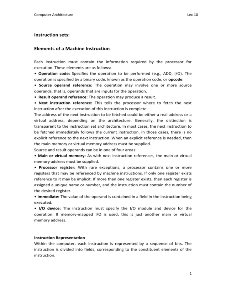
Computer Architecture Lec 10 Instruction sets: Elements of a Machine Instruction Each instruction must contain the information required by the processor for execution. These elements are as follows: • Operation code: Specifies the operation to be performed (e.g., ADD, I/O). The operation is specified by a binary code, known as the operation code, or opcode. • Source operand reference: The operation may involve one or more source operands, that is, operands that are inputs for the operation. • Result operand reference: The operation may produce a result. • Next instruction reference: This tells the processor where to fetch the next instruction after the execution of this instruction is complete. The address of the next instruction to be fetched could be either a real address or a virtual address, depending on the architecture. Generally, the distinction is transparent to the instruction set architecture. In most cases, the next instruction to be fetched immediately follows the current instruction. In those cases, there is no explicit reference to the next instruction. When an explicit reference is needed, then the main memory or virtual memory address must be supplied. Source and result operands can be in one of four areas: • Main or virtual memory: As with next instruction references, the main or virtual memory address must be supplied. • Processor register: With rare exceptions, a processor contains one or more registers that may be referenced by machine instructions. If only one register exists reference to it may be implicit. If more than one register exists, then each register is assigned a unique name or number, and the instruction must contain the number of the desired register. • Immediate: The value of the operand is contained in a field in the instruction being executed. • I/O device: The instruction must specify the I/O module and device for the operation. If memory-mapped I/O is used, this is just another main or virtual memory address. Instruction Representation Within the computer, each instruction is represented by a sequence of bits. The instruction is divided into fields, corresponding to the constituent elements of the instruction. 1 A simple example of an instruction format is shown in Figure 9.1. As another example, During instruction execution, an instruction is read into an instruction register (IR) in the processor. The processor must be able to extract the data from the various instruction fields to perform the required operation. Figure 9.1 a simple instruction format It is difficult for both the programmer and the reader of textbooks to deal with binary representations of machine instructions. Thus, it has become common practice to use a symbolic representation of machine instructions. Opcodes are represented by abbreviations, called mnemonics, that indicate the operation. Common examples include ADD SUB MUL DIV LOAD STOR Add Subtract Multiply Divide Load data from memory Store data to memory Operands are also represented symbolically. For example, the instruction ADD R, Y may mean add the value contained in data location Y to the contents of register R. In this example, Y refers to the address of a location in memory, and R refers to a particular register. Note that the operation is performed on the contents of a location, not on its address. Thus, it is possible to write a machine-language program in symbolic form. Each symbolic opcode has a fixed binary representation, and the programmer specifies the location of each symbolic operand. Most programs today are written in a high-level language or, failing that, assembly language. However, symbolic machine language remains a useful tool for describing machine instructions, and we will use it for that purpose. Instruction Types Consider a high-level language instruction that could be expressed in a language such as BASIC or FORTRAN. For example, X=X+Y 2 This statement instructs the computer to add the value stored in Y to the value stored in X and put the result in X. How might this be accomplished with machine instructions? Let us assume that the variables X and Y correspond to locations 513 and 514. If we assume a simple set of machine instructions, this operation could be accomplished with three instructions: 1. Load a register with the contents of memory location 513. 2. Add the contents of memory location 514 to the register. 3. Store the contents of the register in memory location 513. As can be seen, the single BASIC instruction may require three machine instructions. This is typical of the relationship between a high-level language and a machine language. A high-level language expresses operations in a concise algebraic form, using variables. A machine language expresses operations in a basic form involving the movement of data to or from registers. With this simple example to guide us, let us consider the types of instructions that must be included in a practical computer. A computer should have a set of instructions that allows the user to formulate any data processing task. Another way to view it is to consider the capabilities of a high-level programming language. Any program written in a high-level language must be translated into machine language to be executed. Thus, the set of machine instructions must be sufficient to express any of the instructions from a high-level language. With this in mind we can categorize instruction types as follows: • Data processing: Arithmetic and logic instructions • Data storage: Movement of data into or out of register and or memory locations •Data movement: I/O instructions • Control: Test and branch instructions Arithmetic instructions provide computational capabilities for processing numeric data. Logic (Boolean) instructions operate on the bits of a word as bits rather than as numbers; thus, they provide capabilities for processing any other type of data the user may wish to employ. These operations are performed primarily on data in processor registers. Therefore, there must be memory instructions for moving data between memory and the registers. I/O instructions are needed to transfer programs and data into memory and the results of computations back out to the user. Test instructions are used to test the value of a data word or the status of a computation. Branch instructions are then used to branch to a different set of instructions depending on the decision made 3 Number of Addresses One of the traditional ways of describing processor architecture is in terms of the number of addresses contained in each instruction. This dimension has become less significant with the increasing complexity of processor design. Nevertheless, it is useful at this point to draw and analyze this distinction. What is the maximum number of addresses one might need in an instruction? Evidently, arithmetic and logic instructions will require the most operands. Virtually all arithmetic and logic operations are either unary (one source operand) or binary (two source operands). Thus, we would need a maximum of two addresses to reference source operands. The result of an operation must be stored, suggesting a third address, which defines a destination operand. Finally, after completion of an instruction, the next instruction must be fetched, and its address is needed. This line of reasoning suggests that an instruction could plausibly be required to contain four address references: two source operands, one destination operand, and the address of the next instruction. In most architectures, most instructions have one, two, or three operand addresses, with the address of the next instruction being implicit (obtained from the program counter). Most architecture also has a few special-purpose instructions with more operands. Figure 9.2 example program Figure 9.2 compares typical one-, two-, and three-address instructions that could be used to compute Y = (A - B)/[C + (D * E)] With three addresses, each instruction specifies two source operand locations and a destination operand location. Because we choose not to alter the value of any of the operand locations, a temporary location, T, is used to store some intermediate results. Note that there are four instructions and that the original expression had five operands. 4 Three-address instruction formats are not common because they require a relatively long instruction format to hold the three address references. With two address instructions, and for binary operations, one address must do double duty as both an operand and a result. Simpler yet is the one-address instruction. For this to work, a second address must be implicit. This was common in earlier machines, with the implied address being a processor register known as the accumulator (AC). The accumulator contains one of the operands and is used to store the result. In our example, eight instructions are needed to accomplish the task. TYPES OF OPERANDS Machine instructions operate on data. The most important general categories of data are • Addresses • Numbers • Characters • Logical data In this context, addresses can be considered to be unsigned integers. Other common data types are numbers, characters, and logical data, and each of these is briefly examined in this section. Beyond that, some machines define specialized data types or data structures. For example, there may be machine operations that operate directly on a list or a string of characters. Numbers All machine languages include numeric data types. Even in nonnumeric data processing, there is a need for numbers to act as counters, field widths, and so forth. Three types of numerical data are common in computers: • Binary integer or binary fixed point • Binary floating point • Decimal It remains to say a few words about decimal numbers. Although all internal computer operations are binary in nature, the human users of the system deal with decimal numbers. Thus, there is a necessity to convert from decimal to binary on input and from binary to decimal on output. For applications in which there is a great deal of I/O and comparatively little, comparatively simple computation, it is preferable to store and operate on the numbers in decimal form. The most common representation for this purpose is packed decimal. With packed decimal, each decimal digit is represented by a 4-bit code, in the obvious way, with two digits stored per byte. Thus 0 = 0000, 1 = 0001, … , 8 = 1000 5 Note that this is a rather inefficient code because only 10 of 16 possible 4-bit values are used. To form numbers, 4-bit codes are strung together, usually in multiples of 8 bits. Thus, the code for 246 is 0000 0010 0100 0110. This code is clearly less compact than a straight binary representation, but it avoids the conversion overhead. Negative numbers can be represented by including a 4-bit sign digit at either the left or right end of a string of packed decimal digits. Standard sign values are 1100 for positive+ and 1101 for negativeCharacters A common form of data is text or character strings. While textual data are most convenient for human beings, they cannot, in character form, be easily stored or transmitted by data processing and communications systems. Such systems are designed for binary data. Thus, a number of codes have been devised by which characters are represented by a sequence of bits. Perhaps the earliest common example of this is the Morse code. Today, the most commonly used character code in the International Reference Alphabet (IRA), referred to in the United States as the American Standard Code for Information Interchange (ASCII). Each character in this code is represented by a unique 7-bit pattern; thus, 128 different characters can be represented. This is a larger number than is necessary to represent printable characters, and some of the patterns represent control characters. Some of these control characters have to do with controlling the printing of characters on a page. Others are concerned with communications procedures. IRA-encoded characters are almost always stored and transmitted using 8 bits per character. The eighth bit may be set to 0 or used as a parity bit for error detection. In the latter case, the bit is set such that the total number of binary 1s in each octet is always odd (odd parity) or always even (even parity). Logical Data Normally, each word or other addressable unit (byte, halfword, and so on) is treated as a single unit of data. It is sometimes useful, however, to consider an n-bit unit as consisting of n 1-bit items of data, each item having the value 0 or 1.When data are viewed this way, they are considered to be logical data. There are two advantages to the bit-oriented view. First, we may sometimes wish to store an array of Boolean or binary data items, in which each item can take on only the values 1 (true) and 0 (false).With logical data, memory can be used most efficiently for this storage. Second, there are occasions when we wish to manipulate the bits of a data item. For example, if floating-point operations are implemented in software, we need to be able to shift significant bits in some operations. 6 TYPES OF OPERATIONS The number of different opcodes varies widely from machine to machine. However, the same general types of operations are found on all machines. A useful and typical categorization is the following: • Data transfer • Arithmetic • Logical • Conversion • I/O • System control • Transfer of control ADDRESSING The address field or fields in a typical instruction format are relatively small. We would like to be able to reference a large range of locations in main memory or, for some systems, virtual memory. To achieve this objective, a variety of addressing techniques has been employed. They all involve some trade-off between address range and/or addressing flexibility, on the one hand, and the number of memory references in the instruction and/or the complexity of address calculation, on the other. In this section, we examine the most common addressing techniques: • Immediate • Direct • Indirect • Register • Register indirect • Displacement • Stack 7 Figure 9.3 Addressing mode These modes are illustrated in Figure 9.3. In this section, we use the following notation A = contents of an address field in the instruction R = contents of an address field in the instruction that refers to a register EA = actual (effective) address of the location containing the referenced operand (X) = contents of memory location X or register X 8 Immediate Addressing The simplest form of addressing is immediate addressing, in which the operand value is present in the instruction. Operand = A This mode can be used to define and use constants or set initial values of variables. Typically, the number will be stored in twos complement form; the leftmost bit of the operand field is used as a sign bit. When the operand is loaded into a data register, the sign bit is extended to the left to the full data word size. In some cases, the immediate binary value is interpreted as an unsigned nonnegative integer. The advantage of immediate addressing is that no memory reference other than the instruction fetch is required to obtain the operand, thus saving one memory or cache cycle in the instruction cycle. The disadvantage is that the size of the number is restricted to the size of the address field, which, in most instruction sets, is small compared with the word length. Direct Addressing A very simple form of addressing is direct addressing, in which the address field contains the effective address of the operand: EA = A The technique was common in earlier generations of computers but is not common on contemporary architectures. It requires only one memory reference and no special calculation. The obvious limitation is that it provides only a limited address space. Indirect Addressing With direct addressing, the length of the address field is usually less than the word length, thus limiting the address range. One solution is to have the address field refer to the address of a word in memory, which in turn contains a full-length address of the operand. This is known as indirect addressing: As defined earlier, the parentheses are to be interpreted as meaning contents of. The obvious advantage of this approach is that for a word length of N, an address space of is now available. The disadvantage is that instruction execution requires two memory references to fetch the operand: one to get its address and a second to get its value. Although the number of words that can be addressed is now equal to the number of different effective addresses that may be referenced at any one time is limited to 2K where K is the length of the address field. 9 Register Addressing Register addressing is similar to direct addressing. The only difference is that the address field refers to a register rather than a main memory address: EA = R To clarify, if the contents of a register address field in an instruction is 5, then register R5 is the intended address, and the operand value is contained in R5. Typically, an address field that references registers will have from 3 to 5 bits, so that a total of from 8 to 32 general-purpose registers can be referenced. The advantages of register addressing are that (1) only a small address field is needed in the instruction, and (2) no time-consuming memory references are required. Displacement Addressing A very powerful mode of addressing combines the capabilities of direct addressing and register indirect addressing. It is known by a variety of names depending on the context of its use, but the basic mechanism is the same. We will refer to this as displacement addressing: EA = A + (R) Displacement addressing requires that the instruction have two address fields, at least one of which is explicit. The value contained in one address field (value = A) is used directly. The other address field, or an implicit reference based on opcode, refers to a register whose contents are added to A to produce the effective address. We will describe three of the most common uses of displacement addressing: • Relative addressing • Base-register addressing • Indexing RELATIVE ADDRESSING For relative addressing, also called PC-relative addressing, the implicitly referenced register is the program counter (PC). That is, the next instruction address is added to the address field to produce the EA. Typically, the address field is treated as a twos complement number for this operation. Thus, the effective address is a displacement relative to the address of the instruction. BASE-REGISTER ADDRESSING For base-register addressing, the interpretation is the following: The referenced register contains a main memory address, and the address field contains a displacement (usually an unsigned integer representation) from that address. The register reference may be explicit or implicit. Base-register addressing also exploits the locality of memory references. It is a convenient means of implementing segmentation. 10 In some implementations, a single segment-base register is employed and is used implicitly. In others, the programmer may choose a register to hold the base address of a segment, and the instruction must reference it explicitly. In this latter case, if the length of the address field is K and the number of possible registers is N, then one instruction can reference any one of N areas of words. INDEXING For indexing, the interpretation is typically the following: The address field references a main memory address, and the referenced register contains a positive displacement from that address. Note that this usage is just the opposite of the interpretation for base-register addressing. Of course, it is more than just a matter of user interpretation. Because the address field is considered to be a memory address in indexing, it generally contains more bits than an address field in a comparable base-register instruction. Also, we shall see that there are some refinements to indexing that would not be as useful in the base-register context. Nevertheless, the method of calculating the EA is the same for both base-register addressing and indexing. Stack Addressing The final addressing mode that we consider is stack addressing. a stack is a linear array of locations. It is sometimes referred to as a pushdown list or last-in-first-out queue. The stack is a reserved block of locations. Items are appended to the top of the stack so that, at any given time, the block is partially filled. Associated with the stack is a pointer whose value is the address of the top of the stack. Alternatively, the top two elements of the stack may be in processor registers, in which case the stack pointer references the third element of the stack. The stack pointer is maintained in a register. Thus, references to stack locations in memory are in fact register indirect addresses. The stack mode of addressing is a form of implied addressing. The machine instructions need not include a memory reference but implicitly operate on the top of the stack. 11


