Determine the discharge capacity of a 150 mm diameter coated
advertisement

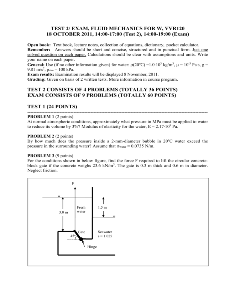
TEST 2/ EXAM, FLUID MECHANICS FOR W, VVR120 18 OCTOBER 2011, 14:00-17:00 (Test 2), 14:00-19:00 (Exam) Open book: Text book, lecture notes, collection of equations, dictionary, pocket calculator. Remember: Answers should be short and concise, structured and in punctual form. Just one solved question on each paper. Calculations should be clear with assumptions and units. Write your name on each paper. General: Use (if no other information given) for water: 20oC) =1.0103 kg/m3, = 10-3 Pas, g = 9.81 m/s2, patm = 100 kPa. Exam results: Examination results will be displayed 8 November, 2011. Grading: Given on basis of 2 written tests. More information in course program. TEST 2 CONSISTS OF 4 PROBLEMS (TOTALLY 36 POINTS) EXAM CONSISTS OF 9 PROBLEMS (TOTALLY 60 POINTS) TEST 1 (24 POINTS) --------------------------------------------------------------------------------------------------------------------PROBLEM 1 (2 points) At normal atmospheric conditions, approximately what pressure in MPa must be applied to water to reduce its volume by 3%? Modulus of elasticity for the water, E = 2.17∙109 Pa. PROBLEM 2 (2 points) By how much does the pressure inside a 2-mm-diameter bubble in 20oC water exceed the pressure in the surrounding water? Assume that σwater = 0.0735 N/m. PROBLEM 3 (9 points) For the conditions shown in below figure, find the force F required to lift the circular concreteblock gate if the concrete weighs 23.6 kN/m3. The gate is 0.3 m thick and 0.6 m in diameter. Neglect friction. F 3.0 m Fresh water 1.5 m Gate Seawater s = 1.025 45o Hinge PROBLEM 4 (6 points) A free water jet is shooting out from a pipe nozzle according to below figure. a) Find the flow rate, b) Find the height h above the nozzle to which the water jet will shoot. Assume no friction loss. Free jet h Nozzle diameter 100 mm 1.1 m A Water Point A; pipe diameter 200 mm, PA = 55 kPa PROBLEM 5 (5 points) A gate is located in a channel according to below figure. a) Find the flow rate per meter width. b) Find the resulting force of water and its direction on the gate. Assume no friction loss. Gate 2.0 m Water 0.8 m WRITTEN TEST 2 (36 POINTS) --------------------------------------------------------------------------------------------------------------------PROBLEM 6 (6 points) Determine the discharge capacity of a 150 mm diameter coated steel pipe to carry water at 20oC if the pressure loss due to friction may not exceed 35 kPa per 100 m of pipe length. PROBLEM 7 (12 points) Lund needs more water! For this purpose the community has identified the Västersjön lake in northern Scania as a clean and reliable water supply source. A minimum flow for economic feasibility is considered to be about 100 L/s through a square section 0.5 m · 0.5 m and 120 km long pipeline. Unfortunately the pipeline has to follow the landscape topography over the Hallandsås according to below estimated elevations (Elev. = elevation in m in below figure) to avoid another Hallandsås scandal. Therefore, a number of pumps with pump curve according to below can be installed along the pipeline. a) Assuming a surface roughness of the pipeline ks = 0.03 mm determine number and possible location of pumps to allow for approximately 100 L/s in the pipeline (note that transect of the pipeline is quadratic according to above). b) The peak of Hallandsås might be a spot for possible cavitation problems. Assuming critical pressure for cavitation here, calculate necessary flow rate for above pumps to avoid cavitation (assume vapour pressure of the water equal to 2 kPa). c) Modify the pump system to allow for the results in b) (if you could not calculate Q in b) use Q=200 L/s). d) Plot a general energy line for the pipeline to be functional (Q can be unspecified). Q (L/s) Head Hp (m) 60 24 80 22 100 20 120 16 140 10 160 5 Elev. +300 m Hallandsås peak Elev. +200 m Elev. +200 m Lund reservoir Lake Västersjön Elev. +150 m 30 km Väster sjön 90 km Västersj ön PROBLEM 8 (10 points) A long rectangular 4 m wide channel with normal water depth has a smooth double-sided constriction that leads to a flow situation according to below figure. a) Explain the flow situation and water level variation before and after the constriction. b) Calculate normal flow rate for a Manning´s n=0.018 and S0= 8.6 · 10-3. c) Calculate y2 (if you could not calculate Q above use Q=16 m3/s). d) Calculate y3 (if you could not calculate Q above use Q=16 m3/s). e) Calculate distance Δx (if you could not calculate y2 and y3 above use y2 =3 m and y3=4 m). Constriction Channel seen from above Water V Channel seen from the side y3 y2 V 0.9 m 0.4 m Δx PROBLEM 9 (8 points) The sphere below the water surface is connected via a rod to the bottom of the channel. a) Describe without calculations what forces are acting on the sphere and their respective direction. b) Determine the force in the rod and the direction of it in relation to the horizontal if the sphere has a diameter of 0.5 m, weighs 1 kg, and V is equal to 5 m/s. (Tip: volume of a sphere is 4·π·r3/3 where r=radius). Sphere V Water Rod Solutions 1. E = -dp/(dV/V); dV/V = -0.03, E = 2.17∙109 Pa; => dp = 2.17∙109 ∙ 0.03 = 0.0651∙109 Pa Answer: 65.1 MPa. 2. Force balance for bubble surrounded by water: 2πrσ=pπr2; where r is bubble radius and p is internal pressure of bubble => p = 2σ/r = 0.0735 ∙ 2/0.001 = 147 N/m2. Answer: pressure must exceed 147 N/m2. 3. Forces: Ff = Total force from freshwater, Fs = Total force from seawater, W = weight of gate, and F. Ff = 9.81∙1000∙(3+((0.62/2)1/2)/2)∙π∙0.32 = 8.9 kN Fs = 9.81∙1025∙(1.5+((0.62/2)1/2)/2)∙π∙0.32 = 4.9 kN W = 23.6·π·0.32·0.3=2 kN Levers: lf, ls, lw, and lF lf = (3·√2+0.6) - LPf = (3·√2+0.6) – (3·√2+0.3 + (π·0.34)/(4·π·0.32·(3·√2+0.3)) = 0.295 m ls = (1.5·√2+0.6) - LPs = (1.5·√2+0.6) – (1.5·√2+0.3 + (π·0.34)/(4·π·0.32·(1.5·√2+0.3))= 0.291 m lw = 0.3/√2 = 0.213 m lF = 0.6/√2 = 0.426 m Moment around hinge: F· lF + Fs · ls = Ff · lf + W· lw => F = (8.9·0.295 + 2 · 0.213 – 4.9 · 0.291)/0.426 = 3.82 kN Answer: F = 3.82 kN. 4. a) Continuity equation between point A and point N (nozzle outlet): VA ·AA = VN · AN => VN = VA ·0.12/0.052 Bernoulli between point A and N: pA/γ + 0 + VA2/2g = 0 + 1.1 + VN2/2g = 55/9.91 + VA2/2g = 1.1 + (VA ·0.12/0.052)2/2g => VA = 2.4 m/s => Q = 2.4 · π · 0.12 = 0.0754 m3/s. Answer: Q = 75.4 L/s. b) Take Bernoulli from point N to top of jet: 0 + 0 + VN2/2g = 0 + h + 0 => h = 0.07542/((π·0.052)2· 2g) = 4.7 m Answer: h = 4.7 m. 5. a) Continuity equation from upstream gate to downstream: Vup· 2·1 = Vdown· 0.8·1 => Vdown = Vup· 2/0.8 Take Bernoulli from upstream gate to downstream: Vup2/2g + 2 + 0 = Vdown2/2g + 0.8 + 0 => Vup = (((Vup· 2/0.8)2/2g – 1.2) 2g)1/2 => Vup = 2.1 m/s => Q = 2.1 · 2 = 4.2 m3/s per width m. Answer: Q = 4.2 m3/s per width m. b) Take a control section from upstream (1) to downstream gate (2) and momentum equation gives (x-coord. to the right, F is reaction force in gate): F1 – F - F2= 1000 · Q (Vdown – Vup) put Vup = V1; Vdown = V2 = 5.3 m/s; F1 = 9810·2; F2= 0.4·9810·0.8= 3139; Inserted in to momentum equation give F = 3.04 kN, Answer: F = 3.04 kN directed to the right. 6. Use the relation Re = VD/ν = V·0.15/(1·10-6) = 1.5 · 105 · V; Test by trial and error for different; ks for coated steel pipe is 0.06 mm (Hamill Table 6.2) => Test 1: Assume V = 3.0 m/s then Re = 1.5 · 105 · 3.0 = 4.5 · 105; ks/D = 0.00006/0.15 = 0.0004; from Moody´s diagram f= 0.018 => hf = f·L·V2/(2·g·D) = P/γ = 35/9.81 = 3.56 m thus 3.56 = 0.018·100·V2/(2·9.81·0.15) => V = 2.4 m/s. Test 2: Assume V = 2.4 m/s then Re = 1.5 · 105 · 2.4 = 3.6 · 105; from Moody´s diagram f= 0.0175 => 3.56 = 0.0175·100·V2/(2·9.81·0.15) => V = 2.45 m/s (ok!). Therefore, Q = A·V = π·0.0752·2.45=0.043 m3/s. Answer: 43 L/s. 7. a) Check flow type. Re = ρ·V·4RH/μ; RH = A/P = 0.5·0.5/(4·0.5) = 0.125; V=Q/A=0.1/0.25=0.4 m/s => Re = 1000·0.4·4·0.125/(1·10-3)=200000; Thus, turbulent. Take the energy equation from the lake to the Lund reservoir (disregard local losses): Hp = hf= HS hf = f·L·Q2/(4·RH·2g·A2) = f·120000·Q2/(4·0.125·2g·0.252)=f∙195719·Q2= HS. ks/(4RH)=0.03·10-3/ (4·0.125) =0.00006 => from Moody´s diagram: Q 60 80 100 120 140 160 Re 120000 160000 200000 240000 280000 320000 f 0.0180 0.0175 0.0170 0.0165 0.0155 0.0150 HS 13 22 33 45 59 75 Plotting the system curve with vertical addition of the pump shows that 2 pumps (in series) could give about 110 L/s, 3 pumps about 125 L/s. Thus, for a minimum flow of 100 L/s 2 pumps would suffice. The location should be just after the lake in order to prevent cavitation problems. Answer: Two pumps in series give about 110 L/s located just after the lake. b) Assume critical pressure -98 at Hallandsåsen. Energy eqn gives: 0+0+0+HP=-98·103/9810+100+Q2/(2g·0.252)+f∙195719·Q2/4 ≈ f∙48930·Q2 = HS2 => Q Re f HS2 60 120000 0.0180 3 80 160000 0.0175 5 100 200000 0.0170 8 120 240000 0.0165 11 140 280000 0.0155 15 160 320000 0.0150 19 Plotting the new system curve with the 2 pumps in series shows that the flow would need to be about 150 L/s to avoid cavitation. Answer: About 150 L/s. c) To achieve that flow in relation to the original system curve either more pumps in series can be added or pumps can be put in parallel until HS ≈ 65 m is reached (150 L/s). 1 pump for a flow of 150 L/s gives approximately 8 m head. Thus, 65/8 gives about 8 pumps in series. Alternatively, putting 8 pumps in parallel would give approximately similar results (fictive pump for 3 serial pumps x 2 + 2 parallel pumps). Answer: 8 pumps in series or parallel with a resulting flow of minimum about 150 L/s. (sorry for bad scan, the parallel option should show 8 pumps in parallel)! d) Energy line should show increase over pumps with influence of friction and reaching Lund reservoir. 8. a) Normal flow is supercritical. The constriction leads to a slow-down of water and supercritical to subcritical flow via a hydraulic jump. The constriction also leads to build-up of water before the constriction. Critical flow occurs at the center of constriction. After that the water accelerates and becomes again supercritical. A minimum water depth occurs at the end of constriction (max velocity). Far downstream the constriction the water depth approaches the normal water depth in an asymptotic way. b) Manning gives V=R2/3·S01/2/n => R=A/P=0.9·4/(2·0.9+4)=0.621 => V=0.6212/3· 0.00861/2/0.018= 3.75 m/s => Q=3.75·0.9·4=13.5 m3/s. Answer: Q=3.75·0.9·4=13.5 m3/s. c) Eqn for hydraulic jump: y2=y1/2(-1 + (1+8F12)1/2); F1 = V/(g·y)1/2 = 3.75/(9.81·0.9)1/2= 1.26 > supercritical. y2=0.9/2(-1+(1+8·1.62)1/2) => y2 = 1.22 m. Answer: y2 = 1.22 m. d) Energy eqn from 3 to 4 gives y3: E3 = E4 (no losses) => y3 + (Q/(4·y3))2/2g = y4 + (Q/(4·y4))2/2g => y3 + 0.581/y32 – 4.03 = 0; T&E => y3 ≈ 4.0 m. Answer: y3 ≈ 4.0 m. e) Use direct step method. Δx=ΔL=(E2-E1)/(S0-Sf); Sf from Manning; Sf = V2· n2/y4/3; section 3 => section 2 (results depend somewhat on number of steps). Section 3 y 4.0 V 0.84 E 4.036 2.76 1.608 ΔE Sf 0.000036 2.428 2 1.22 Answer: Δx≈300 m. SAver Δx 0.000194 290 m 0.000158 9. a) Answer: Forces are: FB = buoyancy – upwards, W = weight – downwards, Frod = force in rod – downwards to the left parallel to the rod, and FD = drag – to the right parallel to water movement. b) FB = 9810·4·π·r3/3 = 641.7 N W = m·g = 9.81 N Frod = ? FD = CD·ρ·V2·A/2; CD from Finnemore&Franzini Fig. 9.10 with Re = V·D/ν = 0.5·5/(1.0·10-6); assume T = 20oC. => Re = 2.5 · 106 => CD ≈ 0.2 => FD = 0.2· 1000· 52 · π∙0.252/2 = 491 N The FB and W are acting in opposite direction. The resulting vertical force is 641.7-9.81= 631.9 N. Frod will balance the resulting force from 631.9 and FD. Thus, Frod = (6322 + 4912)1/2 ≈ 808 N. tanφ=632/491=1.287 => φ=52o. Answer: Rod force is 808 N and angle from horizontal is 52o downwards to the left.


