Startup Procedure Ex..
advertisement

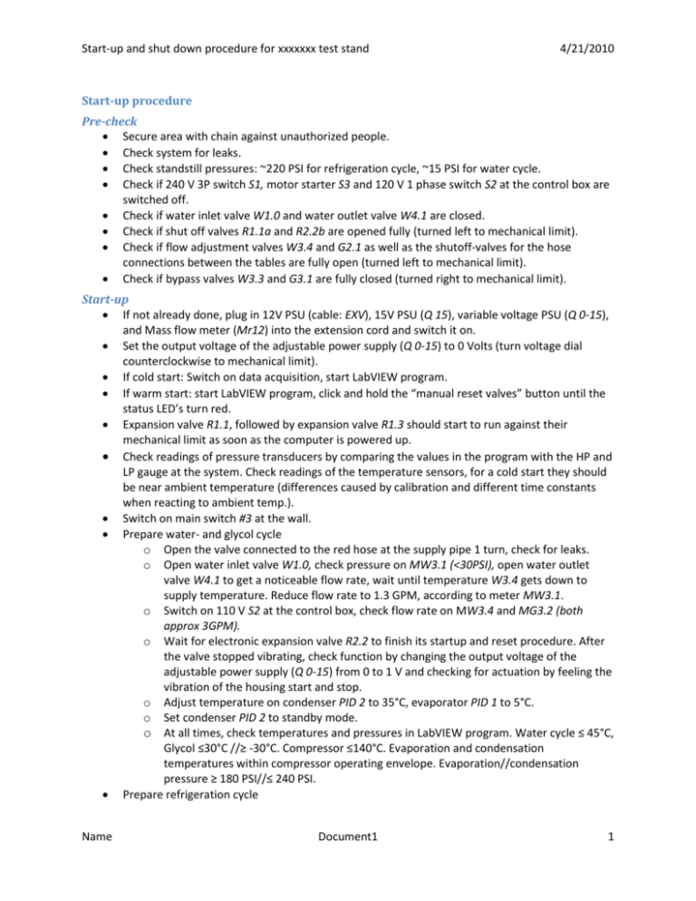
Start-up and shut down procedure for xxxxxxx test stand 4/21/2010 Start-up procedure Pre-check Secure area with chain against unauthorized people. Check system for leaks. Check standstill pressures: ~220 PSI for refrigeration cycle, ~15 PSI for water cycle. Check if 240 V 3P switch S1, motor starter S3 and 120 V 1 phase switch S2 at the control box are switched off. Check if water inlet valve W1.0 and water outlet valve W4.1 are closed. Check if shut off valves R1.1a and R2.2b are opened fully (turned left to mechanical limit). Check if flow adjustment valves W3.4 and G2.1 as well as the shutoff-valves for the hose connections between the tables are fully open (turned left to mechanical limit). Check if bypass valves W3.3 and G3.1 are fully closed (turned right to mechanical limit). Start-up If not already done, plug in 12V PSU (cable: EXV), 15V PSU (Q 15), variable voltage PSU (Q 0-15), and Mass flow meter (Mr12) into the extension cord and switch it on. Set the output voltage of the adjustable power supply (Q 0-15) to 0 Volts (turn voltage dial counterclockwise to mechanical limit). If cold start: Switch on data acquisition, start LabVIEW program. If warm start: start LabVIEW program, click and hold the “manual reset valves” button until the status LED’s turn red. Expansion valve R1.1, followed by expansion valve R1.3 should start to run against their mechanical limit as soon as the computer is powered up. Check readings of pressure transducers by comparing the values in the program with the HP and LP gauge at the system. Check readings of the temperature sensors, for a cold start they should be near ambient temperature (differences caused by calibration and different time constants when reacting to ambient temp.). Switch on main switch #3 at the wall. Prepare water- and glycol cycle o Open the valve connected to the red hose at the supply pipe 1 turn, check for leaks. o Open water inlet valve W1.0, check pressure on MW3.1 (<30PSI), open water outlet valve W4.1 to get a noticeable flow rate, wait until temperature W3.4 gets down to supply temperature. Reduce flow rate to 1.3 GPM, according to meter MW3.1. o Switch on 110 V S2 at the control box, check flow rate on MW3.4 and MG3.2 (both approx 3GPM). o Wait for electronic expansion valve R2.2 to finish its startup and reset procedure. After the valve stopped vibrating, check function by changing the output voltage of the adjustable power supply (Q 0-15) from 0 to 1 V and checking for actuation by feeling the vibration of the housing start and stop. o Adjust temperature on condenser PID 2 to 35°C, evaporator PID 1 to 5°C. o Set condenser PID 2 to standby mode. o At all times, check temperatures and pressures in LabVIEW program. Water cycle ≤ 45°C, Glycol ≤30°C //≥ -30°C. Compressor ≤140°C. Evaporation and condensation temperatures within compressor operating envelope. Evaporation//condensation pressure ≥ 180 PSI//≤ 240 PSI. Prepare refrigeration cycle Name Document1 1 Start-up and shut down procedure for xxxxxxx test stand o o o o o o o o o o 4/21/2010 Close needle valves R4.1 and R4.2, set opening of expansion valve R1.1 to 500 and expansion valve R1.4 to ___ steps in LabVIEW program. Adjust control voltage for expansion valve R2.2 to 0 V to fully close this valve. Wait for all electronic valves to reach their position (green LEDs in LabVIEW program/valves R1.1, R1.3, R2.2 stop vibrating). Switch on 3 phase switch S1. Switch on motor starter S3 to startup compressor. Check temperatures and pressures in LabVIEW program. Temperatures of water cycle should be below 45°C, Temperatures of Glycol cycle should be below 30°C and above 30°C. Compressor discharge temperature should be below 140°C. Evaporation and condensation temperatures should be within the compressor operating envelope. Evaporation pressure should be above 50 PSI//below 171 PSI, condensation pressure should be above 272 PSI//below 450 PSI. Check system for abnormal vibration, switch of S3 if abnormal vibration occurs, then follow shutdown procedure. Determine and fix problem before shutting on the system again. Set condenser PID 2 to operating mode again. Adjust water flow rate//PID set points to keep refrigeration cycle inside of the specified operating range. Adjust R1.4 to reach a superheat of at least 3°C at the compressor inlet. Wait for system to stabilize. Taking data Adjust temperatures of water respectively glycol cycle to reach different condensing/evaporating temperatures. o Adjust mass flow rate, using valves EXV R1.1, EXV R1.3, EXV R2.2, needle valve R4.1 and R4.2 and Needle valve R2.2b to reach a reasonable superheat at the compressor inlet (3…20°C). If using R2.2b or R2.2, first close them fully, the open the upstream shut off valves and then open them to the required degree. At all times, check temperatures and pressures in LabVIEW program. Temperatures of water cycle should be below 45°C, Temperatures of Glycol cycle should be below 30°C and above 30°C. Compressor discharge temperature should be below 140°C. Evaporation and condensation temperatures should be within the compressor operating envelope. Evaporation pressure should be above 50 PSI//below 171 PSI, condensation pressure should be above 272 PSI//below 450 PSI. Use water bypass valve W3.3 to adjust flow rate in order to reach different subcooling values for the condenser. Volume flow rate on MW3.4 should never be smaller than 0.5 GPM. If condensing temperature rises/falls above/below the set point of PID 2, increase/reduce water flow rate at water outlet valve W4.1. Wait for the system to get to stable conditions before setting the “steady flag”. Remove the “steady flag” before approaching the next data point. Shut down Switch off motor starter S3 to shut down compressor. Check temperatures and pressures in LabVIEW program. Temperatures of water cycle should be below 45°C, Temperatures of Glycol cycle should be below 30°C and above -30°C. Compressor discharge temperature should be below 140°C. Evaporation and condensation temperatures should approach the standstill pressure of ~220PSI (use HP/LP gauge to check trend). Set both PID controllers on standby. Name Document1 2 Start-up and shut down procedure for xxxxxxx test stand 4/21/2010 Wait for 1 minute to remove all heat from the heater coils, and then switch off 110 V S2. Set opening of electronic expansion valves R1.1 and R1.3 to 200 steps in LabVIEW program. Switch of 3 phase switch S1, then switch of switch #3 at the wall. Close water outlet valve W4.1, then close water inlet valve W1.0 and then close the faucet at the sink. Open stepper valves R1.1 and R1.3 200 steps (prevent liquid from being trapped). Open valves R2.2b (needle~) and R2.2 (EXV) for the same reason. Close the upstream shut off valves Switch of the power supplies and the data acquisition (order not important). Cool-down procedure Prevent access to compressor by setting up chains accordingly. Attach warning signs “Hot surfaces, do not enter” to the chains. Monitor compressor top temperature in LabVIEW program. Remove sign and chain after this temperature is down to 50°C. ! Emergency shut down Switch off motor starter S2, and then switch off 3 Phase switch S1. Switch off main switch #3 at wall, and then switch of the extension cord at the experimental setup. Potential Hazards: Electric shock: May result from a broken power cable Hot water spill Cold glycol spill Hot surfaces: compressor, discharge lines Safety Equipment: Protective glasses Contact Info: Christian Bach (Rm 77): 765-494-2147 (after hours: 765-426-7804) Prof. James E. Braun (Rm 30): 765 49-49157 Emergency Contact: Prof. James E. Braun (Rm 30): 765 49-49157 Bob Brown (Rm 55 - Shop): 765–714–1818 (after hours: 765-426-8900) Judy Hanks (Rm 47): 765-494-2129 Rm 55 - Shop: 765-49-42142 In Case of Fire: There are 4 fire extinguishers in the West Wing 1 (ABC) at the entrance of the Hudelson room 1 (BC) at the entrance to office Rm 30 1 (BC) at the entrance of psychrometric room 1 (ABC) between the dock door and the mailbox Name Document1 3


