Chapter 13
2001, W. E. Haisler Chapter 13: Beam Bending
Deflection and Stress Analysis in Beam Bending
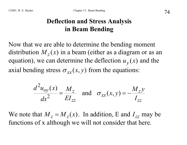
Now that we are able to determine the bending moment distribution M z
( ) in a beam (either as a diagram or as an equation), we can determine the deflection u y
( ) and the axial bending stress
xx x y from the equations: d u oy
( )
M dx
2
EI z zz
and
xx x y
I zz
We note that M z
M z
( ) . In addition, E and I zz
may be functions of x although we will not consider that here.
74
2001, W. E. Haisler Chapter 13: Beam Bending
Example 1. Cantilever beam with end load, F
F
EI = constant
V y
L x
The shear and moment diagrams (and equations) are:
M z
V y
( )
F
F FL
M z
( )
(
x ) x x
L L
75
2001, W. E. Haisler Chapter 13: Beam Bending oy dx
2
M z
(
x )
EI zz
Integrate ODE twice to obtain
EI zz u oy
( )
F
EI zz
[ Lx
2
/ 2
x
3
/ 6]
1
2 where C
1
and C
2
= constants of integration .
Apply B.C. (fixed from displacement and rotation at x=0): u oy
( x
0) 0 C
2
=> C
2
= 0 du oy
( x
0)
0 C
1
=> C
1
= 0 dx
76
2001, W. E. Haisler Chapter 13: Beam Bending 77
Thus, the transverse displacement is u oy
( )
F
[ Lx
2
/ 2
x
3
/ 6]
Fx
2
2 EI zz
[ L
x / 3]
EI zz
The displacement at the end is given by: u oy
( )
3
FL
3
EI zz
Solve for stress:
xx
M y
(
)
I zz
I zz
Maximum normal stress is at x=0 and y = +/- max value. At y = +max value (top surface),
xx
is negative (compressive).
Suppose the beam is a hollow steel tube with OD=1" and
ID=0.75" and has a length of 6 ft. F=20 lbf.
2001, W. E. Haisler Chapter 13: Beam Bending 78
I zz
( D
4 o
D i
4
64
4
64
4
) (1 0.75 )
0.034
in
4 u oy
( )
FL
3
lb in
3 x
6 psi ).034
in
4
2.4
in
3 EI zz
xx
( x
0, y
0.5)
I zz x
0, y
.5
(
I
zz
) x
0, y
.5
20 (72 in
0)0.5
in
21.2
ksi
0.034
in
4
note: axial stress is compressive on top!
2001, W. E. Haisler Chapter 13: Beam Bending
Deflection Example 2. Cantilever beam with uniform distributed load, p
0 p o
E, I = constant
79
L
V y x
M z
V y
( )
(
x ) p L
2
/ 2
M z
( )
(
x ) / 2 x
L L
Write the deflection equation for the moment above: x
2001, W. E. Haisler Chapter 13: Beam Bending oy dx
2
M z
EI zz
Integrate ODE twice to obtain u oy
( )
po
2 EI zz
[ / 2
p o
( L
EI x zz
Lx
3
/ 3
x
4
/12]
C x
C
2
Apply B.C. (x=0 is fixed from displacement and rotation): u oy
( x
0) 0 C
2
=> C
2
0 du oy
( x
0)
C
2
0 => C
1
0 dx
Thus transverse displacement is
80
2001, W. E. Haisler Chapter 13: Beam Bending u oy
( )
p o
[ / 2
Lx
3
/ 3
x
4
/12]
2 EI zz
Note, displacement at the tip (x=L) is:
Solve for stress:
xx u oy
( )
p L
4
8 EI zz
My
I zz
[ p L
x ) / 2] y
I zz
For a given cross-section with I z
about z axis, max axial stress is at x=0 and y = +/- max value. At y = +max value
(top surface),
xx
is negative (compressive).
81
2001, W. E. Haisler Chapter 13: Beam Bending
Recitation Exercise #1:
For each case determine the displacement boundary conditions. a)
75 lbf 100 lbf b)
100 lbf
75 lbf c) x
8 in
20 in
75 lbf 100 in-lbf d)
82 x
8 in
20 in
75 lbf 100 in-lbf x
8 in
20 in x
8 in
6 in
20 in
2001, W. E. Haisler e) x
20 in f)
1,000 lb x
10 in g)
500 in-lb x
20 in
10 in
Chapter 13: Beam Bending
50 lb/in
10 in
50 lb/in
10 in
50 lb/in
500 in-lb
10 in
83
2001, W. E. Haisler Chapter 13: Beam Bending
Deflection Example 3. Simply Supported Beam with
Distributed Normal Load p o
Assume EI = constant
L
NO MOMENTS AT ENDS
WITH SIMPLE SUPPORTS x
From equilibrium: R
1
= R
2
= p o
L/2.
V z
/ 2
M z x
L
M x
p
0
L
/ 2) ( x
)
Deflection equation becomes
84
2001, W. E. Haisler Chapter 13: Beam Bending dx
2 oy
M
EI zz
( p o
/ 2) (
L )
EI zz
Integrate ODE twice to obtain
3 u oy
( )
[ x
2 ]
C x
C
2
24 EI zz
Apply B.C. ( oy
0 u
at x=0 and x=L): u oy
( x
0) 0 C
2
=> C
2
0 u oy
( x
L ) 0 o
3
24 EI zz
[ L
L
C L
=> C
1
p L
3
/(24 EI z
)
85
2001, W. E. Haisler Chapter 13: Beam Bending 86
Thus transverse displacement is u oy
( )
po
[ x
4
2 x L
xL
3
]
24 EI zz
Note: u oy
( / 2)
(5 / 384) p L
4
EI zz
Solve for stress:
xx
I zz
[( p o
/ 2) (
)]
I zz
For a given cross-section with I about z axis, max stress is at x=L/2 and y = +/- max value. At y = +max value (top surface),
xx
is negative (compression).
0
8
2001, W. E. Haisler Chapter 13: Beam Bending 87
Deflection Example 4. Cantilever beam with 2 shear forces
75 lbf 100 lbf x
8 in
20 in
V y
(lbf) M z
(ft-lbf)
100 1,400
25 x
8 ” 20”
8 ” x 8" : M z
( )
1, 400
x in
lbf x 20" : M z
( )
2, 000 100
1,200
20” x
2001, W. E. Haisler Chapter 13: Beam Bending 88
The deflection equation becomes dx
0 y
2
M
EI z zz
with M z
8"
20"
Because we have two equations for the bending moment, we will
(
( have two solutions to the differential equation. In region 1
0
8" x x
8" ), call the solution
20"
1
), call the solution
( )
2
; and in region 2
( )
Each differential equation will have its
.
8" own boundary conditions. At the left ( )
( ) end, the beam is cantilevered. At x=8, we have “ interface
” type boundary conditions (similar to heat transfer) that relate ( ) and ( ) . at x
0 u
1
(0)
0 du
1
(0)
0 dx at x
8 u
1
(8)
u
2
(8) du
1
(8)
dx du
2
(8) dx x
2001, W. E. Haisler Chapter 13: Beam Bending 89
Region 1. Integrate ODE with moment from x=0 to x=8".
Call this solution u
1
(for region 1). d u
1
M dx
2
EI z 1 zz
EI zz x
( )
[700 x
2
25 x
3
/ 6
2
]/( EI zz
)
B.C. at x=0 are displacement
Apply B.C. and u oy
0 and slope
C
1
C
2
0 . Hence for 0 du oy
0 . x dx
8" , we have
( )
[700 x
2
25 x
3
/ 6]/ EI zz for 0 x 8 "
2001, W. E. Haisler Chapter 13: Beam Bending 90
Region 2. Integrate ODE with moment from x=8 to 20". d u
2
M dx
2
EI z zz
2
EI zz x
( )
[1,000 x
2
100 x
3
/ 6
4
]/( EI zz
)
for 8 x 20"
B.C. for above is that displacement and slope at x=8" in region 2 must match the displacement and slope solution in region 1at the point x=8" ( interface boundary conditions ):
(
8)
1
(
8) ….......(1)
(
8) dx
du x
8) dx
……..(2)
2001, W. E. Haisler Chapter 13: Beam Bending
Applying these interface B.C.s
gives
(1): u
2
(8)
[1,000(8)
2
100(8) / 6
C
3
(8)
u
1
(8)
[700(8)
2
25(8) / 6]/( EI zz
)
C
4
]/( EI zz
) du
2
(8)
(2): dx
C
3
]/( EI zz
)
du
1
(8) dx
EI zz
)
Solving for C
3
and
3
C
4
gives
C
2, 400 , C
4
6, 400
Hence, ( ) becomes
91
2001, W. E. Haisler Chapter 13: Beam Bending 92 u
2
( )
u oy x
[1,000 x
2
100 x
3
/ 6
2, 400 x
6, 400]/( EI zz
)
for 8 20"
The displacement at the tip (x=20") is equal to u oy
( x
20")
u x
20)
225,067 /( EI z
)
Suppose the beam is made of steel with a rectangular crosssection of b=0.5" and h=2" ( I zz
bh
3
/12
0.333
in
4
), then u oy
( x
20")
x
6 psi )(0.333
in
4
)]
0.023"
Displacement at x=20” is positive, and thus upwards.
2001, W. E. Haisler Chapter 13: Beam Bending
The two displacement solutions may be plotted to obtain: u
2
( )
93
( )
2001, W. E. Haisler Chapter 13: Beam Bending 94
Stress is given by:
xx
I zz
with M z
8"
20"
At x=0, y=-1" (bottom of beam)
xx
I zz
1, 400
0.333
in
4 at x=10", y=+1" (top of beam)
xx
(10,1)
I zz
1,000 in lb ( 1")
0.333
in
4
4, 200 psi ( tension )
3,333 psi ( comp ) at x=15", y=+1" (top of beam)
xx
(15,1)
I zz
500 in lb ( 1")
0.333
in
4
1,667 psi ( comp )
2001, W. E. Haisler Chapter 13: Beam Bending 95
Example 4 again - Solve for V & M by integration [solve for all constants simultaneously]. Same for u oy
( ) [solve for displacement in both sections simultaneously].
75 lbf 100 lbf x
1 2
8 in
20 in
Define section 1 to be x=0 to x=8" and section 2 to be x=8 to x=20".
Section 1: dV
1 dx dM
1
p y
C
1
1
( )
2 dx
0
V x
C
1
2001, W. E. Haisler Chapter 13: Beam Bending 96
Section 2: dV
2 dx dM
2 dx
p y
0
C
3
V x
M
2
C
( )
3
4
B.C.s for V & M:
At x=20: V
2
(20)
100
C
3
(1) , M
2
(20) 0 C
3
(20)
C
4
(2)
75
M
1
(8) M
2
(8)
At x=8: Freebody at x=8":
Must observe positive directions for V & M!!
V
1
(8)
75
V
2
(8)
C
1
75
C
3
(3)
V
1
(8) x=8”
M
1
(8)
M
2
(8)
C
1
(8)
C
2
C
3
(8)
C
4
(4)
V
2
(8)
2001, W. E. Haisler Chapter 13: Beam Bending 97
Solving equation (1-4) for the 4 constants simultaneously gives:
C
1
25; C
2
1, 400; C
3
100; C
4
2, 000
Hence, V and M are:
( )
lb V x
lb
( )
25 x
1, 400 in
lbf
M
2 x
100 x
2, 000
Now solve for the deflection equations in each section:
Section 1:
EI zz
EI u
1 dx
2
1
M
1
25 x
1, 400
x
3 x
2
25 / 6 1, 400 / 2
5
6
2001, W. E. Haisler Chapter 13: Beam Bending 98
Section 2:
EI zz
EI u
2 dx
2
2
M
2
100 x
2000
100 x
3
/ 6
2000 x
2
/ 2
7
8
BCs for displacement:
At x=0 (fixed):
Displacement is zero:
zz
(
0) 0 C
6
….(5)
Slope is zero:
EI zz du
1
( x
0)
C
5
….(6
) dx
At x=8 (interface):
Displacements are equal:
zz
(
8)
zz
(
8)
2001, W. E. Haisler Chapter 13: Beam Bending 99
3 2
C
5
(8)
C
6
3
100(8) / 6
2
2000(8) / 2
C
7
(8)
C
8
. .(7)
Slopes are equal:
EI zz du
1
( x
8)
dx
EI zz du
2
( x
8) dx
C
5
100(8) / 2
2000(8)
C
7
…(8)
Solving the equations (5-8)for the 4 constants gives:
C
5
0, C
6
0, C
7
2400, C
8
6400
2001, W. E. Haisler Chapter 13: Beam Bending 100 and the displacement equations are given by:
( )
1
EI zz
25 x
3 x
2
/ 2
in u
2
( )
1
EI zz
100 x
3
/ 6
2000 x
2 x
6, 400
in
Notice that we solved equations (1-4) for the constants in V
& M; and then solved equations (5-8) for the constants in u
1 and u
2
. However, we could have left V & M in terms of constants ( C
1
C
4
), and solved for these constants (so now u
1
and u
2 u
1
and u
2
in terms of
in terms of C
1
C
8
) and solved for all 8 constants simultaneously.
2001, W. E. Haisler Chapter 13: Beam Bending
101
Use of Maple to obtain
V & M equations, and displacement equation.
Example 4 (same as before):
Solves for V, M and uy.
Problem is defined for points x1 to x3. x1 is left end, x3 is right end and x2 is a point in between.
P2 is force applied at x2 (positive is up), P3 is force applied at x3.
M2 is moment applied at x3 (positive is CCW), M3 is moment applied at x3. p12 is distributed load (force/length) from x1 to x2 (positive is up), p23 is distributed load from x2 to x3.
V12 and V23 are shear from x1 to x2 and x2 to x3, respectively.
M12 and M23 are moment from x1 to x2 and x2 to x3, respectively. sol1=uy(x)=deflection equation (up is positive)
> with(plots):with(DEtools):
> restart;
> x1:=0;x2:=8;P2:=-75; M2:=0; x3:=20; P3:=100; M3:=0; p12:=0; p23:=0;
# not needed P1:=-25;M1:=-1400; x1 := 0 x2 := 8
P2 := -75
M2 := 0 x3 := 20
P3 := 100
M3 := 0 p12 := 0 p23 := 0
> V23:=P3+int(p23,x=x..x3);
V23 := 100
> V12:=subs(x=x2,V23)+P2+int(p12,x=x..x2);
V12 := 25
> M23:=M3+int(V23,x=x..x3);
M23 := 2000
100 x
> M12:=subs(x=x2,M23)+M2+int(V12,x=x..x2);
M12 := 1400
25 x
> V:= piecewise(x>=x1 and x<x2,V12,x>=x2 and x<x3,V23,x=x3,V23-P3);
2001, W. E. Haisler
V :=
Chapter 13: Beam Bending
25
100
0
x
0 and x
8
8
x
0 and x
20 x
20
102
> M:= piecewise(x>=x1 and x<x2,M12,x>=x2 and x<x3,M23,x=x3,M23-M3);
1400
25 x
x
0 and x
8
M := 2000
100 x 8
x
0 and x
20
2000
100 x x
20
> plot(V(x),x=x1..x3,title="Shear Diagram",labels=["x","V(x)"]);
> plot(M(x),x=x1..x3,title="Moment Diagram",labels=["x","M(x)"]);
> E:=30*10^6;Izz:=0.333;
2001, W. E. Haisler Chapter 13: Beam Bending
E := 30000000
Izz := .333
> deq1:=diff(uy(x),x$2)=M/(E*Izz);
2 deq1 :=
x
2 uy x
.1001001001 10
-6
1400
25 x
2000
100 x
2000
100 x
x
0 and x
8
8
x
0 and x
20 x
20
103
> sol1:=evalf(dsolve({deq1,uy(x1)=0,D(uy)(x1)=0},uy(x))); sol1 := uy ( )
{ 0.
, x
0.
.00007007007007
x
2
.4170837504 10
-6 x
3
, x
8.
.0001001001001
x
2
.1668335002 10
-5 x
20.
.01270603937
.001761761762
x , 20.
x
3
x
.0006406406406
.0002402402402
x ,
> plot(rhs(sol1),x=x1..x3,title="Displacement",labels=["x","uy(x)"]);
> evalf(subs(x=x1,sol1)); evalf(subs(x=x2,sol1)); evalf(subs(x=x3,sol1)); uy 0
0.
uy 8
.004270937604
uy 20 )
.02252919586
2001, W. E. Haisler Chapter 13: Beam Bending
104
Use of MDSolids to obtain
V & M equations, and displacement equation.
MDSolids can be used to determine moments of inertia for many cross-sections, determine V&M diagrams for cantilevered and simple supported beams, and determine the deflection due to these loads.
Example 4 (same as before):
We consider the same example 4. In order to determine deflections, the section properties (A, I, etc.) must first be defined using the
“Section Properties” module of MDSolids. A screen shot of this module is shown on the next page. Then, the beam type (cantilever or simple supported) and loads must be defined using the “Determinate
Beams” module. This module will provide plots of shear and moment diagrams, as well as the deflected shape of the beam. Screen shots of these results are shown below. Actually, MDSolids may be used to solve more complex beam bending and torsion problems using the
“General Analysis” module.
2001, W. E. Haisler Chapter 13: Beam Bending
105
2001, W. E. Haisler Chapter 13: Beam Bending
106
2001, W. E. Haisler Chapter 13: Beam Bending
107
