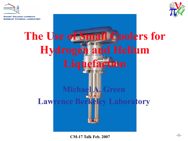
The Use of Small Coolers for Hydrogen and Helium
advertisement

The Use of Small Coolers for Hydrogen and Helium Liquefaction Michael A. Green Lawrence Berkeley Laboratory CM-17 Talk Feb. 2007 -1- Why is liquefaction with a cooler a problem? • The heat of vaporization for hydrogen and helium is much lower than the heat that must be removed to cool the gas to the liquefaction temperature. • For helium the heat of vaporization is 20.7 J g-1. The sensible heat from 300 K to 4 K is 1540 J g-1. A perfect helium liquefier has refrigeration to liquefaction coefficient of 20.7 J g-1. • For hydrogen the heat of vaporization is 445 J g-1. The sensible heat from 300 K to 20 K is ~4000 J g-1. A perfect hydrogen liquefier has refrigeration to liquefaction coefficient of 445 J g-1. • Hydrogen is easier to liquefy with a cooler than helium. CM-17 Talk Feb. 2007 -2- 2-Stage GM Cooler with an Added J-T Loop JT Circuit Compressor Cooler Compressor GM Cooler Motor & Drive Unit Vacuum Vessel 1st Stage Displacer 1st Stage T = 50 to 60 K 2nd Stage Displacer 2nd Stage T = 10 to 12 K J-T Valve Helium Tank CM-17 Talk Feb. 2007 -3- Liquefaction with a separate J-T loop. • Refrigeration at 4 K is relatively easy even when the cooler can only produce 8 K at the 2nd-stage. Liquefaction of helium is nearly impossible. Recondensation is not the same as liquefaction. The refrigeration to liquefaction coefficients for helium are greater 500 J g-1. • The advent of 4 K coolers improved liquefaction with a separate J-T circuit, but to refrigeration to liquefaction coefficients are still high (~350 J g-1). • Liquefaction of hydrogen is easier. CM-17 Talk Feb. 2007 -4- 2-Stage 4 K GM Cooler used as Liquefier CM-17 Talk Feb. 2007 -5- Liquefaction with a 4 K GM Cooler • Liquefaction with a 4 K cooler is possible if there is a larger heat exchanger on the 2nd-stage. • Adding a heat exchanger to to the 1st-stage greatly improves liquefaction of helium. The refrigeration to liquefaction coefficient is ~ 160 J g-1. Adding liquid nitrogen cooling improve liquefaction even more. • In theory, a refrigeration to liquefaction coefficient of 600 J g-1 can be achieved for hydrogen. CM-17 Talk Feb. 2007 -6- Additional Cooling can come off of the Regenerator and Pulse tubes of a Cryomech Pulse Tube Cooler to Compressor to Compressor Rotary Valve Rotary Valve Vacuum Vessel Vacuum Vessel Regenerator Tube Regenerator Tube T = 60 K Q = 20 W Pulse Tube Q = 20 W Q = 1.25 W Q = 0.50 W T = 4.2 K T = 60 K Q = 0.38 W a) Unmodified 0.5 W Cooler CM-17 Talk Feb. 2007 Pulse Tube T=8K T = 4.2 K b) 0.5 W Cooler with an Intercept beteen Stages -7- One can get additional cooling from the tubes of Cryomech pulse tube coolers • The experiment at Cryomech using a PT-405 cooler showed that additional cooling is available between stages from the regenerator tube and the pulse tube. • Cooling between stages is not available for a typical GM cooler. Not all pulse tube coolers have cooling available between stages. • The cooling between stages can greatly improve the liquefaction efficiency (a lower refrigeration to liquefaction coefficient). CM-17 Talk Feb. 2007 -8- Circuit Diagram for the PT-410 Liquefier with Tube Heat Exchanger to Compressor Rotary Valve He Gas Vacuum Vessel Regenerator Tube T = 60 K 1st Stage Pre-cooler Pulse Tube Tube Heat Exchanger T = 4.2 K He Condenser He Vessel LHe out CM-17 Talk Feb. 2007 -9- PT-410 Liquefier with Tube Heat Exchanger Condensing Pot Cooler 2nd-Stage Tube Heat Exchanger Cooler 1st-Stage 1st Stage Heat Exchanger Rotary Valve Rotary Valve Motor Ballast Tank CM-17 Talk Feb. 2007 -10- Liquefaction with the PT-410 Cooler • The heat exchanger on the 1st-stage and the heat exchanger on the regenerator tube between the 1st and 2nd stages of a PT-410 cooler reduces the refrigeration to liquefaction coefficient of 45 J g-1 for helium. This is better than any other helium liquefier. • Cooling from the tubes between stage permits one to operate the PT-415 cooler in the drop in mode because there is free-convection between the mounting tube and the cooler. CM-17 Talk Feb. 2007 -11- Drop In PT-415 Cooler with Condenser for the MICE Tracker Solenoids Cooler Ballast Tank Valve Motor Rotary Valve Cooler Top Plate Cryostat Top Plate Radiation Shield Seal Cooler Tube Pulse Tube Connects to Shields Regenerator Tube Cooler Ist Stage with Taper He Gas He Gas from Magnet Condenser (Area = 0.042 m 2) LHe to Magnet CM-17 Talk Feb. 2007 -12- The drop in cooler concept will be used for the PT-415 cooler for the MICE tracker solenoid. • It is hoped that free-convection cooling between the cooler tubes and the mounting tube will reduce the heat leak down the mounting tube. • The mounting tube wall thickness will be machined down from 0.87 mm to 0.37 mm. • The 1st-stage tapered joint allows heat from the leads, the thermal radiation shield, and the cold mass supports to the cooler 1st stage. CM-17 Talk Feb. 2007 -13- Cryomech found that the liquefaction improved without the tube heat exchanger. • Eliminating the heat exchanger from the cooler liquefier reduces the cost of the liquefier. • Eliminating the heat exchanger from the cooler liquefier increases the efficiency of liquefaction about 30 percent. The new Cryomech liquefier has a refrigeration to liquefaction coefficient of 36 J g-1. • Cryomech would like to build the hydrogen (helium) liquefier for the MICE absorbers. CM-17 Talk Feb. 2007 -14- A More Efficient Liquefier without the Tube Heat Exchanger The areas shown are based on the PT-415 cooler. CM-17 Talk Feb. 2007 -15- The Proposed Cryomech Absorber Hydrogen Liquefaction System Using the PT-415 Cooler CM-17 Talk Feb. 2007 -16- A Proposed Absorber Cooler Module • Cryomech has a commercial interest in building a hydrogen liquefier. • Cryomech proposes to use the pulse tubes and regenerator tubes and holes in the first stage to pre-cool the hydrogen being liquefied. Standard tube parts would be used for the liquefier. • Hydrogen from the hydride bed (or bottles) must be fed into the upper part of the cooler space between the top plate and the first stage heat exchanger • The absorber probably can be filled in 24 hours. CM-17 Talk Feb. 2007 -17- An End View of a Proposed MICE Absorber Cooler Module with Hydrogen Liquefier Cooler Ballast Tank Hydrogen Gas Fill Line Valve Motor Rotary Valve Liquefier Top Plate Seal Radiation Shield Pulse Tube Liquefier Tube 1st Stage Area = 0.04 m 2 ) Tube Area = 0.07 m 2 Space between Wall & 1st Stage = 25 m Regenerator Tube Absober cooler Neck Space between Wall & condenser = 1 mm Condenser (Area = 0.06 m2 ) Tube Area = 0.06 m 2 30 to 40 K Shield 25 mm ID 25 mm ID 15 mm ID 15 mm ID f rom Absorber Top to Absorber Bottom CM-17 Talk Feb. 2007 -18- A Proposed Cooler Experiment Using the PT-415 Cooler CM-17 Talk Feb. 2007 -19- Purpose of the Cooler Experiment • Measure the performance of the PT-415 cooler in the magnet configuration over a range of 2nd-stage temperatures from 2.5 K to about 22 K and 1st-stage temperatures from 30 K to 65 K. • Confirm the that the PT-415 cooler will will work well in the drop in configuration. Measure the extra heat leak (if any) that comes from this method of mounting the cooler in this way. • Demonstrate that the PT-415 cooler will liquefy both helium and hydrogen. CM-17 Talk Feb. 2007 -20- Known Operating Points of the PT-415 Cooler SECOND STAGE TEMPERATURE, K SECOND STAGE TEMPERATURE K 6 6 55 44 33 22 25 0 W 21W 3.0W 84W 63W 42W 2.5W 2.0W 1.5W 1.0W 0.5W 0W CRYOMECH TEST 35 45 55 65 75 FIRST STAGE TEMPERATURE, K The measured test data is from Tom Painter of Florida State University. CM-17 Talk Feb. 2007 -21- Plans for the Cooler Experiment • This experiment will measure the temperature of both stages of a PT-415 pulse tube cooler as a function of the heat load on both stages. On the first stage power with Q = 0, 20, 40, 60 and 80 W will be applied. At that same time, the second stage power will be changed in steps of Q = 0, 0.5, 1.0, 1.5, 2.0, 5, 10, 15, 20, 25, and 30 W. • The measurements will be done both in vacuum and in a helium gas atmosphere. • The experiment will compare the thermal resistance of the first stage taper boundary in vacuum and in helium gas CM-17 Talk Feb. 2007 -22- Cooler Experiment Purpose Continued • The degree to which convection currents play a role in intercepting heat will be measured by recording the temperature on the tube between stages both in vacuum and in helium. • With liquid helium in the tank, the DT between the tank and the second stage cold head will be measured. • Operate the cryogenic system with the cooler with helium at 3.8 K, 4.2 K and 4.6 K. • Measure the liquefaction of helium at 4.3 K. • Measure the liquefaction of hydrogen at 20.8 K. CM-17 Talk Feb. 2007 -23- Diagram of a Proposed Cooler Experiment CM-17 Talk Feb. 2007 -24- What is needed for the experiment? • One MICE PT-415 cooler for a magnet • The actual magnet cooler mounting tube • A liquefaction vessel (~1.5 liters) for He and H2 • A 1st stage thermal shield with MLI inside and outside the shield to minimize heat leak • The experiment vacuum vessel • Seven (or eight) diode temperature sensors T • Two 1st Stage heaters Q (0 to 80 watts) • Two 2nd Stage heaters Q (0 to 30 watts) • Commercial LHe and LH2 liquid level gauges CM-17 Talk Feb. 2007 -25- Concluding Comments • Hydrogen liquefaction is possible with both GM and pulse tube coolers. Liquefaction must be done correctly. • Cryomech has proposed that the could fabricate the absorber hydrogen liquefaction module. This may be cost effective. • A test of the PT-415 cooler is needed, even for the tracker magnet. If LBL doesn’t do the test, who will do the test? CM-17 Talk Feb. 2007 -26-


