40993 053D Commercial Unit Ground and First Floor Plans
advertisement
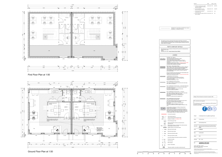
Revision: Date: Drawn: Check: A First floor removed as per client's comments. Potential to retrofit a first floor indicated. 18/11/2021 KTB SJD/AYA B Layout amended in line with Structural Engineer's drawings. 06/01/2021 KTB AYA/RTS C Drawing status amended for construction issue 02/11/2022 JAK AYA D Service entry points added, staircase 09/12/2022 AYA layout updated 16,978 16,528 5,483 63 300 2,250 2,250 63 5,463 328 327 122 328 328 328 450 Toilets D08 D11 D12 6,075 D07 Dashed line to denotes possible future layout alterations - Allowed for by S.E. Void 328 665 Office 93 Office This drawing to be read in conjunction with the client's requirements, structural & consulting engineers drawings & details, and Building Control. Movement joint positions for exact requirements and positions refer to structural engineers drawings. Ensure that all party walls are fire stopped. D09 D05 2,134 1,915 Void 9,215 63 110 svp boxed in and sound insulated 63 8,765 110 svp boxed in and sound insulated 6,075 Toilets D10 110 svp boxed in and sound insulated 3,769 3,769 D06 110 svp boxed in and sound insulated JER 572 PART E COMPLIANT DETAILS 63 All construction to be in accordance with Approved Document E the following Robust Details should be used: Houses: Separating Party Walls - Robust Standard Detail E-WM-26 3,140 1,810 1,416 2,485 Void CW02 Void EXTERNAL WALL (BRICK) 103mm facing brickwork to BS 3921 FL quality, 125mm Knauf Supafil 34 full fill insulation, 100mm Besblock Star Performer blockwork (to SE spec.) 12.5mm Gypsum Wallboard (8kg/m2) mounted on dabs and 3mm skim. Total structural wall thickness 328mm. 'U' value of 0.23 W/m²K TBC All external walls with render to include bed reinforcement in accordance with manufacturers information 665 CW03 328 CW04 123 328 328 LEGEND CW01 328 5,483 63 2,250 5,953 300 1,585 2,250 1,217 63 3,100 1,585 328 3,499 2,485 665 328 1,810 13,838 PARTY WALL - Robust Detail E-WM-26 100mm Besblock "Start Performer" Blockwork (Density 1528 kg/m³), 100mm (128mm where under external wall) cavity fully filled with mineral wool roll, quilt, or batt with a density of 12-25kg/m3 100mm Besblock "Start Performer" Blockwork (Density 1528 kg/m³), 12.5mm plasterboard (nominal 10kg/m²) mounted on dabs plus 3mm skim both sides. 665 3,140 16,978 Cavity to be stopped at party wall junction with vertical flexible closer (suitable for fire & sound) and vertical DPC. Total structural wall thickness 300mm. 'U' value of 0.00 W/m²K TBC First Floor Plan at 1:50 LOADBEARING PARTITION WALL 100mm wide dense concrete blockwork (to SE spec.) 12.5mm gypsum wallboard on dabs on both sides and 3mm skim on both sides. Total structural wall thickness 100mm. 16,978 1,810 300 7,796 gas 4,383 110 svp boxed in and sound insulated 3,393 328 gas 110 svp boxed in and sound insulated 15mm Gyproc Wallboard (9.8kg/m2) and 3mm skim to both sides of 63 x 38mm CLS studwork. 450 328 122 NON LOADBEARING PARTITION WALL - MOISTURE RESISTANT 328 1,064 1,810 W07 D04 5,747 BC comments are required. This drawing is to be read in conjunction with structural engineers package. r gp Provide pattress to all fixtures and fittings including kitchen / bathroom units and radiators. All walls, ducts and boxings to the accessible WC/cloakroom, bathroom/shower room should be strong enough to support grab rails, seats and other adaptions that could impose a load of up to 1.5kN/m2. Lovell detail to walls ducts and boxings, as a minimum in a band between 300mm and 1800mm above floor level. 9,215 1,810 W08 6 1 7 2 8 3 9 4 10 11 13 12 11 10 5 9 4 Meeting Room 8 3 12 15mm Gyproc MR (on the face of 'wet areas') and 3mm skim to 63 x 38mm CLS studwork filled with one layer 50mm Acoustic Roll to provide min 40RwdB acoustic performance, 15mm Gyproc Wallboard (9.8kg/m2) and 3mm skim. Construct to all bathrooms and WCs adjacent to bedroom, living room. 110 svp boxed in and sound insulated, transferred to corner 7 2 13 potential for stairs to be retrofitted false wall Meeting Room Water, BT and internet connection locations TBC. NON LOADBEARING PARTITION WALL ACOUSTIC & MOISTURE RESISTANT 6 1 8,110 15mm Gyproc Wallboard (9.8kg/m2) and 3mm skim to both sides of 63 x 38mm CLS studwork filled with one layer 50mm Acoustic Roll to provide min 40RwdB acoustic performance. Construct to all walls governed by Regulation E2. 166 D02 1,000 166 false wall 110 svp boxed in and sound insulated, transferred to corner 3,338 NON LOADBEARING PARTITION WALL - ACOUSTIC Kitchen Toilet (Disabled) Toilet (Disabled) 1,000 Kitchen W04 1,810 1,064 elec 5 865 elec potential for stairs to be retrofitted 30 minute fire protection 880 350 910 Outlined meeting room walls to be removed to allow for future stair, if needed Ex D01 W09 Ex D02 328 W01 3,140 1,810 665 328 123 W02 background ventilator (min 5000mm²) TBC BOILER 328 665 tel tel 7,796 1,810 665 1,810 300 1,003 1,585 1,217 13,838 1,585 1,003 328 1,810 686 665 2,485 1,810 Construction Wall-mounted Electric meter box (provide lintel and cavity tray over) Client: GS Developments Boiler position with flue, (min 300mm from window structural opening edge and internal corners) Sheet title: Commercial Unit Ground and First Floor Plans Below gound water supply Scale: 1:50@A1 gas Below ground gas supply elec Below ground electrical supply Date: 13/10/2021 tel Below ground telecom supply Drawn: KTB Checked: RTS AYA Ref: 40993/053D Ground floor fittings to have direct connections connections Water 5,414 Status: Ground bearing gas meter water CW01 water A development at Loughborough Road, Radiator position (to suit furniture layout) 942 Void 2,485 Refer to Farrrow Walsh layouts (S.E.) for support and required steel beams and columns. CW02 flue Project: ceiling mounted extract fan and duct route Elec Void 328 wall mounted extract fan gas W03 1,810 Outlined meeting room walls to be removed to allow for future stair, if needed D03 350 328 910 wef cef vent 665 D01 450 9,215 15mm Gyproc MR (on the face of 'wet areas') and 3mm skim to 63 x 38mm CLS studwork, 15mm Gyproc Wallboard (9.8kg/m2) and 3mm skim. Construct to all bathrooms and WCs. W06 328 W05 4,015 6,075 328 4,847 724 1,810 850 4,046 NON LOADBEARING PARTITION WALL 328 rwp Rainwater downpipe svp Soil & vent pipe b.i.g. Back inlet gully 665 SD 3,140 SD HD Smoke / Heat detector London | Birmingham | Leicester 0203 327 0381 | 0121 309 0071 | 0116 204 5800 rg-p.co.uk · design@rg-p.co.uk Telescopic underfloor vent position (substructure plan) 16,978 All designs should be constructed in strict accordance with building regulations. In addition any materials, components and fixings in/or connected to a façade should be noncombustible if the top storey of the building is above 11m. Ground Floor Plan at 1:50 0 1 2 3 4 5 6 7 8 9 10 All dimensions to be checked on site. Do not scale off this drawing for construction purposes. This drawing is the copyright of the Architect, and not to be reproduced without their permission. Ordnance Survey map information reproduced with permission of HMSO Crown Copyright reserved. rg+p Ltd. Trading as rg+p.
