Application example
advertisement
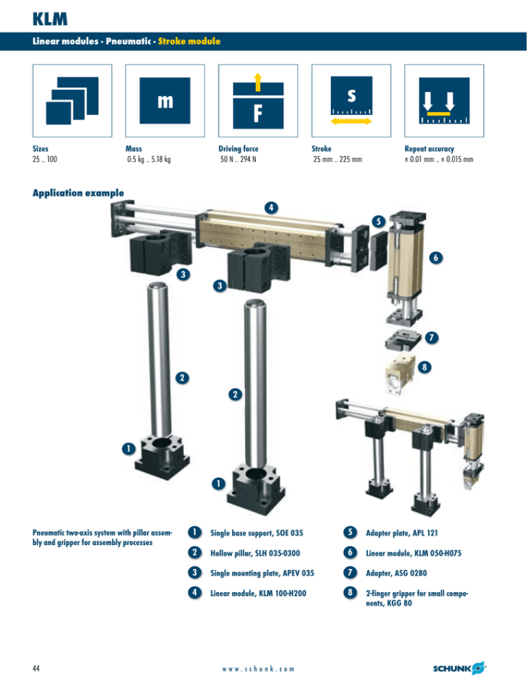
KLM Linear modules · Pneumatic · Stroke module Sizes 25 .. 100 Mass 0.5 kg .. 5.18 kg Driving force 50 N .. 294 N Stroke 25 mm .. 225 mm Repeat accuracy ± 0.01 mm .. ± 0.015 mm Application example 4 5 6 3 3 7 8 2 2 1 1 Pneumatic two-axis system with pillar assembly and gripper for assembly processes 44 1 Single base support, SOE 035 5 Adapter plate, APL 121 2 Hollow pillar, SLH 035-0300 6 Linear module, KLM 050-H075 3 Single mounting plate, APEV 035 7 Adapter, ASG 0280 4 Linear module, KLM 100-H200 8 2-finger gripper for small components, KGG 80 www.schunk.com KLM Linear modules · Pneumatic · Stroke module Stroke module With pneumatic drive and ball bushing guide Area of application For use in clean and slightly dirty environments. Simple economic linear movements or, in combination, as multi-axis positioning systems for assembly and handling technology Advantages – your benefits Double bearing of the guide shafts in the ball bushing For high load bearing capacity and repeat accuracy < 0.015 mm Shock absorber and proximity switch integrated in the projecting areas For vibration-free movements and end-position monitoring Heavy-duty sized guide shafts For high rigidity High basic load ratings In all load directions Standardized mounting bores For numerous combinations with other GEMOTEC system elements Several intermediate positions possible For maximum flexibility in applications Level control by means of rod lock For safety in case of emergency stops General information about the series Guidance Ball bushing guide Material Body Aluminium, hard-anodized Actuation Pneumatic, via filtered compressed air (10 µm): dry, lubricated, or non-lubricated Pressurizing medium: requirements for compressed air quality class according to DIN ISO 8573-1: Quality class 4 Ambient temperature range From 5°C to 60°C Operating pressure range 2 bar to 8 bar Scope of delivery Shock absorber and driver for proximity switch Warranty 24 months Rod lock Can be retrofitted by using a kit For production reasons, the colors may vary from those shown in the catalog. www.schunk.com 45 KLM Linear modules · Pneumatic · Stroke module Cross-section of function 1 Ball bushing guide With wiper; minimal backlash and low friction 3 Modular design hole pattern Completely integrated in the module system 2 Drive Powerful piston rod cylinder 4 Dampening adjustment Adjustment of the dampening characteristic 5 End position setting Convenient adjustment using the shock absorber threads 6 Sensor systems With sensor driver for convenient adjustment Description of function Options and special information The linear module is driven via a double-acting pneumatic cylinder which is integrated in the base body and guided by two opposing guide rods. Fall protection version Prevents the structure from falling in the event of a sudden loss of energy. This module can be combined as standard with many elements from the modular system. You can find more information in the “Accessories” chapter. 46 www.schunk.com KLM Linear modules · Pneumatic · Stroke module Accessories Intermediate stop, ZZA Fittings Rod lock, ASP Adapter plates Accessories from SCHUNK – the ideal components for the best functionality, reliability, and controlled production for all automation modules. Centering strips Sensor cable Inductive proximity switch, NI Pillar assembly systems Pressure maintenance valve Please see the side views at the end of the respective size for information concerning specific sizes, accessories availability for that size, designation, and ID numbers. You can find more information about our accessories program in the “Accessories” part of the catalog. General information about the series Repeat accuracy Repeat accuracy is defined as the distribution of the end positions for 100 consecutive cycles. Travel times The travel times are pure movement times of the slide or the base body. Valve switching times, hose filling times, or PLC reaction times are not a part of this and are to be considered when cycle times are calculated. Stroke The stroke is the maximum nominal stroke of the unit. This can shortened on both sides by the shock absorbers. Layout or sizing For layout or sizing of linear modules, we recommend using our TOOLBOX sizing software, which can be obtained at www.schunk.com. Sizing the selected unit is absolutely necessary, since otherwise overloading can result. Ambient conditions The modules are designed mainly for use in clean ambient conditions. Please note that the life span of the modules can be shortened if they are used in harsh ambient conditions and that SCHUNK cannot assume liability in such cases. Please contact us for assistance. www.schunk.com 47 KLM 25 Linear modules · Pneumatic · Stroke module Moment load Designation KLM 025-H025 KLM 025-H042 KLM 025-H059 Fy/Fz [N] 103 74 59 Mx [Nm] 1.3 1 0.7 My [Nm] 3.2 2.8 2.6 Mz [Nm] 3.2 2.8 2.6 L = 20 mm The forces and moments shown here are maximum values for individual loading. If more than one force or moment occurs simultaneously, the application can be calculated by the TOOLBOX sizing software. Technical data Designation Stroke length Extend force [FV] at 6 bar Retract force [FR] at 6 bar Piston diameter Rod diameter Overall length Mass Fluid consumption/10 mm stroke Minimum pressure Maximum pressure Nominal operating pressure IP rating Min. ambient temperature Max. ambient temperature Repeat accuracy Horizontal travel time at 1 kg additional load Vertical travel time at 1 kg additional load 48 ID [mm] [N] [N] [mm] [mm] [mm] [kg] [cm³] [bar] [bar] [bar] [°C] [°C] [mm] [s] [s] KLM 25-H025 0314010 25 67 50 12 6 135 0.5 1.13 3 8 6 40 5 60 ± 0.01 0.17 0.17 www.schunk.com KLM 25-H042 0314011 42 67 50 12 6 169 0.58 1.13 3 8 6 40 5 60 ± 0.01 0.18 0.18 KLM 25-H059 0314012 59 67 50 12 6 203 0.66 1.13 3 8 6 40 5 60 ± 0.01 0.19 0.19 KLM 25 Linear modules · Pneumatic · Linear axis Main views, KLM 25-H025 A, a B, b 1 2 Main and direct connections, extend linear unit Main and direct connections, retract linear unit Connection, linear unit Connection of the assembly On both attachment faces Back Stroke variants The linear module can be fastened either to the base body or the face plates. The structure can also optionally be fastened to either the face plates or the base body. This view shows the mounting of the module to the base body and the mounting of the structure to the face plates. Variable dimensions of stroke variants Type KLM 25-H025 KLM 25-H042 KLM 25-H059 Stroke [mm] 25 42 59 A [mm] 135 169 203 C [mm] 1x34 1x34 2x34 D [mm] 18…43 18…60 18…77 E [mm] 74 91 108 G [mm] 43…18 60…18 77…18 Not all dimensions shown can be seen in the main view. www.schunk.com 49 KLM 25 Linear modules · Pneumatic · Stroke module Fine adjustment Stroke Stroke adjustment range Dampening stroke adjustment range This illustration shows the possibility of the stroke fine adjustment. Intermediate stop, ZZA on the piston side Intermediate stop, ZZA on the rod side Air connection Intermediate stroke Overall length “A”, the variant without intermediate stroke (see dimension table of stroke variants) Air connection Intermediate stroke Overall length “A”, the variant without intermediate stroke (see dimension table of stroke variants) ZZA 28 Holding force at 6 bar Additional mass at 0 mm stroke Additional mass per mm stroke [N] [kg] [kg] 54 0.2 0.002 Sample order KLM 25-H59-ZZA028-H15 The intermediate position is measured from the respective end position. The intermediate position can be approached from both sides and can proceed in the original stroke direction.. The holding force is the piston force of the intermediate stop less the piston force of the linear module. ZZA 29 Holding force at 6 bar Additional mass at 0 mm stroke Additional mass per mm stroke 54 0.2 0.002 Sample order KLM 25-H59-ZZA029-H15 The intermediate position is measured from the respective end position. The intermediate position can be approached from both sides and can proceed in the original stroke direction.. The holding force is the piston force of the intermediate stop less the piston force of the linear module. You can find further information and components for the accessories mentioned here in the “Accessories” part of the catalog. 50 [N] [kg] [kg] www.schunk.com KLM 25 Linear modules · Pneumatic · Stroke module Sensor systems End-position monitoring: Inductive proximity switch, can be directly mounted Designation ID NI 10 0313427 Extension cable for proximity switch Designation ID Remark STV 10 0313432 Sleeve M8x1, straight STV 20 0313433 Sleeve M8x1, angled G enerally, two sensors are needed for each linear unit. For additional monitoring of the intermediate positions, one sensor per additional position as well as (optionally) one extension cable will be needed. Deflection under load: fa Deflection under load: fb fa in mm fb in mm Stroke in mm Stroke in mm You can find further information and components for the accessories mentioned here in the “Accessories” part of the catalog. www.schunk.com 51 KLM 50 Linear modules · Pneumatic · Stroke module Moment load Designation KLM 050-H013 KLM 050-H025 KLM 050-H038 KLM 050-H050 KLM 050-H063 KLM 050-H075 KLM 050-H088 KLM 050-H100 KLM 050-H113 KLM 050-H125 Fy/Fz [N] 335 335 231 231 166 166 139 139 112 112 Mx [Nm] 6.5 6.5 4.4 4.4 3.4 3.4 2.6 2.6 2.1 2.1 My [Nm] 12.1 12.1 10.2 10.2 9.2 9.2 8.6 8.6 8.2 8.2 Mz [Nm] 12.1 12.1 10.2 10.2 9.2 9.2 8.6 8.6 8.2 8.2 L = 32.5 mm The forces and moments shown here are maximum values for individual loading. If more than one force or moment occurs simultaneously, the application can be calculated by the TOOLBOX sizing software. Technical data Designation Stroke length Extend force [FV] at 6 bar Retract force [FR] at 6 bar Piston diameter Rod diameter Overall length Mass Fluid consumption/10 mm stroke Minimum pressure Maximum pressure Nominal operating pressure IP rating Min. ambient temperature Max. ambient temperature Repeat accuracy Horizontal travel time at 2 kg additional load Vertical travel time at 2 kg additional load OPTIONS and their characteristics Fall protection version Designation Stroke loss of nominal stroke (on the rod side) Mass Static holding force Max. axial backlash of the clamping ZZA intermediate stop on the rod side possible ZZA intermediate stop on the piston side possible LMZAW intermediate stop possible 52 ID [mm] [N] [N] [mm] [mm] [mm] [kg] [cm³] [bar] [bar] [bar] [°C] [°C] [mm] [s] [s] ID [mm] [kg] [N] [mm] KLM 50-H013 0314013 13 120 103 16 6 150 1.3 2 3 8 6 40 5 60 ± 0.01 0.09 0.1 KLM 50-H025 0314014 25 120 103 16 6 150 1.3 2 3 8 6 40 5 60 ± 0.01 0.1 0.11 KLM 50-H038 0314015 38 120 103 16 6 200 1.5 2 3 8 6 40 5 60 ± 0.01 0.11 0.12 KLM 50-H050 0314016 50 120 103 16 6 200 1.5 2 3 8 6 40 5 60 ± 0.01 0.13 0.13 0314414 KLM 50-H025-ASP 10 1.34 180 0.2 Yes Yes No 0314415 KLM 50-H038-ASP 10 1.54 180 0.2 Yes Yes No 0314416 KLM 50-H050-ASP 10 1.54 180 0.2 Yes Yes No www.schunk.com KLM 50 Linear modules · Pneumatic · Stroke module KLM 50-H063 0314017 63 120 103 16 6 250 1.7 2 3 8 6 40 5 60 ± 0.01 0.14 0.14 KLM 50-H075 0314018 75 120 103 16 6 250 1.7 2 3 8 6 40 5 60 ± 0.01 0.15 0.15 KLM 50-H088 0314019 88 120 103 16 6 300 1.9 2 3 8 6 40 5 60 ± 0.01 0.16 0.16 KLM 50-H100 0314020 100 120 103 16 6 300 1.9 2 3 8 6 40 5 60 ± 0.01 0.17 0.17 KLM 50-H113 0314021 113 120 103 16 6 350 2.1 2 3 8 6 40 5 60 ± 0.01 0.19 0.19 KLM 50-H125 0314022 125 120 103 16 6 350 2.1 2 3 8 6 40 5 60 ± 0.01 0.21 0.21 0314417 KLM 50-H063-ASP 10 1.74 180 0.2 Yes Yes No 0314418 KLM 50-H075-ASP 10 1.74 180 0.2 Yes Yes No 0314419 KLM 50-H088-ASP 10 1.94 180 0.2 Yes Yes No 0314420 KLM 50-H100-ASP 10 1.94 180 0.2 Yes Yes No 0314421 KLM 50-H113-ASP 10 2.14 180 0.2 Yes Yes No 0314422 KLM 50-H125-ASP 10 2.14 180 0.2 Yes Yes No www.schunk.com 53 KLM 50 Linear modules · Pneumatic · Stroke module Main views, KLM 50-H013 A, a B, b 1 2 Main and direct connections, extend linear unit Main and direct connections, retract linear unit Connection, linear unit Connection of the assembly On both attachment faces Back Through-bores in the face plate and thread in the base body (only single sided) Stroke variants The linear module can be fastened either to the base body or the face plates. The structure can also optionally be fastened to either the face plates or the base body. This view shows the mounting of the module to the base body and the mounting of the structure to the face plates. Variable dimensions of stroke variants Type KLM 50-H013 KLM 50-H025 KLM 50-H038 KLM 50-H050 KLM 50-H063 KLM 50-H075 KLM 50-H088 KLM 50-H100 KLM 50-H113 KLM 50-H125 Stroke [mm] 13 25 38 50 63 75 88 100 113 125 A [mm] 150 150 200 200 250 250 300 300 350 350 Not all dimensions shown can be seen in the main view. You can find further information and components for the accessories mentioned here in the “Accessories” part of the catalog. 54 www.schunk.com C [mm] 1x25 1x25 2x25 2x25 3x25 3x25 4x25 4x25 5x25 5x25 D [mm] 21…34 21…46 21…59 21…71 21…84 21…96 21…109 21…121 21…134 21…146 E [mm] 83 83 108 108 133 133 158 158 183 183 G [mm] 46…33 46…21 71…33 71…21 96…33 96…21 121…33 121…21 146…33 146…21 KLM 50 Linear modules · Pneumatic · Stroke module Fine adjustment Fine adjustment Stroke Stroke adjustment range Dampening stroke adjustment range Stroke Stroke adjustment range Dampening stroke adjustment range Shock absorbers can be mounted either on the base body or on the face plates. This illustration shows the mounting on the base body and the possibility of stroke fine adjustment. Shock absorbers can be mounted either on the base body or on the face plates. This illustration shows the mounting on the face plates and the possibility of stroke fine adjustment. Rod lock Variable dimensions of rod lock Type KLM 50-H025 KLM 50-H038 KLM 50-H050 KLM 50-H063 KLM 50-H075 KLM 50-H088 KLM 50-H100 KLM 50-H113 KLM 50-H125 Stroke [mm] 15 28 40 53 65 78 90 103 115 D [mm] 21…36 21…49 21…61 21…74 21…86 21…99 21…111 21…124 21…136 E [mm] 93 118 118 143 143 168 168 193 193 G [mm] 36…21 61…33 61…21 86…33 86…21 111…33 111…21 136…33 136…21 Air connection, rod lock The rod lock prevents weights from falling in the event of energy loss, such as emergency stop situations. The rod lock can also be retrofitted, but this will reduce the useful stroke. You can find further information and components for the accessories mentioned here in the “Accessories” part of the catalog. www.schunk.com 55 KLM 50 Linear modules · Pneumatic · Stroke module Intermediate stop, ZZA on the piston side Intermediate stop, ZZA on the piston rod side Air connection Intermediate stroke Overall length “A”, the variant without intermediate stroke (see dimension table of stroke variants) Air connection Intermediate stroke Overall length “A”, the variant without intermediate stroke (see dimension table of stroke variants) ZZA 55 Holding force at 6 bar Additional mass at 0 mm stroke Additional mass per mm stroke [N] [kg] [kg] 175 0.35 0.003 Sample order KLM 50-H100-ZZA055-H30 The intermediate position is measured from the respective end position. The intermediate position can be approached from both sides and can proceed in the original stroke direction.. The holding force is the piston force of the intermediate stop less the piston force of the linear module. ZZA 56 Holding force at 6 bar Additional mass at 0 mm stroke Additional mass per mm stroke 175 0.35 0.003 Sample order KLM 50-H100-ZZA056-H30 The intermediate position is measured from the respective end position. The intermediate position can be approached from both sides and can proceed in the original stroke direction.. The holding force is the piston force of the intermediate stop less the piston force of the linear module. Sensor systems End-position monitoring: Inductive proximity switch, can be directly mounted Designation ID NI 10 0313427 Extension cable for proximity switch Designation ID Remark STV 10 0313432 Sleeve M8x1, straight STV 20 0313433 Sleeve M8x1, angled G enerally, two sensors are needed for each linear unit. For additional monitoring of the intermediate positions, one sensor per additional position as well as (optionally) one extension cable will be needed. You can find further information and components for the accessories mentioned here in the “Accessories” part of the catalog. 56 [N] [kg] [kg] www.schunk.com KLM 50 Linear modules · Pneumatic · Stroke module Deflection under load: fa Deflection under load: fb fa in mm fb in mm Stroke in mm Stroke in mm You can find further information and components for the accessories mentioned here in the “Accessories” part of the catalog. www.schunk.com 57 KLM 100 Linear modules · Pneumatic · Stroke module Moment load Designation KLM 100-H025 KLM 100-H050 KLM 100-H075 KLM 100-H100 KLM 100-H125 KLM 100-H150 KLM 100-H175 KLM 100-H200 KLM 100-H225 Fy/Fz [N] 712 485 485 351 351 256 256 200 200 Mx [Nm] 17.7 12 12 8.7 8.7 6.3 6.3 4.9 4.9 My [Nm] 28 28.1 28.1 27 27 24.5 24.5 22.9 22.9 Mz [Nm] 28 28.1 28.1 27 27 24.5 24.5 22.9 22.9 L = 44 mm The forces and moments shown here are maximum values for individual loading. If more than one force or moment occurs simultaneously, the application can be calculated by the TOOLBOX sizing software. Technical data Designation Stroke length Extend force [FV] at 6 bar Retract force [FR] at 6 bar Piston diameter Rod diameter Overall length Mass Fluid consumption/10 mm stroke Minimum pressure Maximum pressure Nominal operating pressure IP rating Min. ambient temperature Max. ambient temperature Repeat accuracy Horizontal travel time at 3 kg additional load Vertical travel time at 3 kg additional load OPTIONS and their characteristics Fall protection version Designation Stroke loss of nominal stroke (on the rod side) Mass Static holding force Max. axial backlash of the clamping ZZA intermediate stop on the rod side possible ZZA intermediate stop on the piston side possible LMZAW intermediate stop possible 58 ID [mm] [N] [N] [mm] [mm] [mm] [kg] [cm³] [bar] [bar] [bar] [°C] [°C] [mm] [s] [s] ID [mm] [kg] [N] [mm] KLM 100-H025 0314023 25 294 226 25 12 170 2.3 4.9 3 8 6 40 5 60 ± 0.015 0.1 0.12 KLM 100-H050 0314024 50 294 226 25 12 270 3.0 4.9 3 8 6 40 5 60 ± 0.015 0.13 0.14 KLM 100-H075 0314025 75 294 226 25 12 270 3.0 4.9 3 8 6 40 5 60 ± 0.015 0.16 0.16 KLM 100-H100 0314026 100 294 226 25 12 370 3.7 4.9 3 8 6 40 5 60 ± 0.015 0.19 0.19 0314424 KLM 100-H050-ASP 12 3.08 600 0.25 Yes Yes No 0314425 KLM 100-H075-ASP 12 3.08 600 0.25 Yes Yes No 0314426 KLM 100-H100-ASP 12 3.78 600 0.25 Yes Yes No www.schunk.com KLM 100 Linear modules · Pneumatic · Stroke module KLM 100-H125 0314027 125 294 226 25 12 370 3.7 4.9 3 8 6 40 5 60 ± 0.015 0.22 0.22 KLM 100-H150 0314028 150 294 226 25 12 470 4.4 4.9 3 8 6 40 5 60 ± 0.015 0.25 0.25 KLM 100-H175 0314029 175 294 226 25 12 470 4.4 4.9 3 8 6 40 5 60 ± 0.015 0.28 0.28 KLM 100-H200 0314030 200 294 226 25 12 570 5.1 4.9 3 8 6 40 5 60 ± 0.015 0.31 0.31 KLM 100-H225 0314031 225 294 226 25 12 570 5.1 4.9 3 8 6 40 5 60 ± 0.015 0.34 0.34 0314427 KLM 100-H125-ASP 12 3.78 600 0.25 Yes Yes No 0314428 KLM 100-H150-ASP 12 4.48 600 0.25 Yes Yes No 0314429 KLM 100-H175-ASP 12 4.48 600 0.25 Yes Yes No 0314430 KLM 100-H200-ASP 12 5.18 600 0.25 Yes Yes No 0314431 KLM 100-H225-ASP 12 5.18 600 0.25 Yes Yes No www.schunk.com 59 KLM 100 Linear modules · Pneumatic · Stroke module Main views, KLM 100-H025 A, a B, b 1 2 Main and direct connections, extend linear unit Main and direct connections, retract linear unit Connection, linear unit Connection of the assembly On both attachment faces Back Through-bores in the face plate and thread in the base body (only single sided) Sensors and shock absorbers can also be fastened to the back. For variant H025, the sensors, shock absorbers, and the air connections have to be fastened crosswise. Stroke variants The linear module can be fastened either to the base body or the face plates. The structure can also optionally be fastened to either the face plates or the base body. This view shows the mounting of the module to the base body and the mounting of the structure to the face plates. Variable dimensions of stroke variants Type KLM 100-H025 KLM 100-H050 KLM 100-H075 KLM 100-H100 KLM 100-H125 KLM 100-H150 KLM 100-H175 KLM 100-H200 KLM 100-H225 Stroke [mm] 25 50 75 100 125 150 175 200 225 A [mm] 170 270 270 370 370 470 470 570 570 Not all dimensions shown can be seen in the main view. You can find further information and components for the accessories mentioned here in the “Accessories” part of the catalog. 60 www.schunk.com C [mm] 1x25 3x25 3x25 5x25 5x25 7x25 7x25 9x25 9x25 D [mm] 25…50 25…75 25…100 25…125 25…150 25…175 25…200 25…225 25…250 E [mm] 95 145 145 195 195 245 245 295 295 G [mm] 50…25 100…50 100…25 150…50 150…25 200…50 200…25 250…50 250…25 KLM 100 Linear modules · Pneumatic · Stroke module Fine adjustment Fine adjustment Stroke Stroke adjustment range Dampening stroke adjustment range Stroke Stroke adjustment range Dampening stroke adjustment range Shock absorbers can be mounted either on the base body or on the face plates. This illustration shows the mounting on the base body and the possibility of stroke fine adjustment. Shock absorbers can be mounted either on the base body or on the face plates. This illustration shows the mounting on the face plates and the possibility of stroke fine adjustment. Rod lock Variable dimensions of rod lock Type KLM 100-H050 KLM 100-H075 KLM 100-H100 KLM 100-H125 KLM 100-H150 KLM 100-H175 KLM 100-H200 KLM 100-H225 Stroke [mm] 38 63 88 113 138 163 188 213 D [mm] 25…63 25…88 25…113 25…138 25…163 25…188 25…213 25…238 E [mm] 157 157 207 207 257 257 307 307 G [mm] 88…50 88…25 138…50 138…25 188…50 188…25 238…50 238…25 Air connection, rod lock The rod lock prevents weights from falling in the event of energy loss, such as emergency stop situations. The rod lock can also be retrofitted, but this will reduce the useful stroke. You can find further information and components for the accessories mentioned here in the “Accessories” part of the catalog. www.schunk.com 61 KLM 100 Linear modules · Pneumatic · Stroke module Intermediate stop, ZZA on the piston side Intermediate stop, ZZA on the piston rod side Air connection Intermediate stroke Overall length “A”, the variant without intermediate stroke (see dimension table of stroke variants) Air connection Intermediate stroke Overall length “A”, the variant without intermediate stroke (see dimension table of stroke variants) ZZA 105 Holding force at 6 bar Additional mass at 0 mm stroke Additional mass per mm stroke [N] [kg] [kg] 460 0.75 0.006 Sample order KLM 100-H100-ZZA105-H30 The intermediate position is measured from the respective end position. The intermediate position can be approached from both sides and can proceed in the original stroke direction.. The holding force is the piston force of the intermediate stop less the piston force of the linear module. ZZA 106 Holding force at 6 bar Additional mass at 0 mm stroke Additional mass per mm stroke 460 0.75 0.006 Sample order KLM 100-H100-ZZA106-H30 The intermediate position is measured from the respective end position. The intermediate position can be approached from both sides and can proceed in the original stroke direction.. The holding force is the piston force of the intermediate stop less the piston force of the linear module. Inductive attachment, NHS End-position monitoring: Inductive proximity switch, can be directly mounted Designation ID NI 30-KT 0313429 Extension cable for proximity switch Designation ID Remark STV 10 0313432 Sleeve M8x1, straight STV 20 0313433 Sleeve M8x1, angled G enerally, two sensors are needed for each linear unit. For additional monitoring of the intermediate positions, one sensor per additional position as well as (optionally) one extension cable will be needed. You can find further information and components for the accessories mentioned here in the “Accessories” part of the catalog. 62 [N] [kg] [kg] www.schunk.com KLM 100 Linear modules · Pneumatic · Stroke module Deflection under load: fa Deflection under load: fb fa in mm fb in mm Stroke in mm Stroke in mm You can find further information and components for the accessories mentioned here in the “Accessories” part of the catalog. www.schunk.com 63
