GRUV-HE-GB, GRUV6-HE-GB Installation Instructions
advertisement
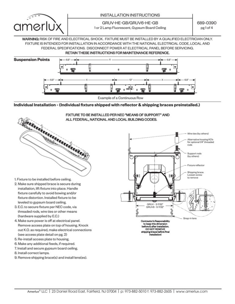
INSTALLATION INSTRUCTIONS GRUV-HE-GB/GRUV6-HE-GB 689-0390 1 or 2 Lamp Fluorescent, Gypsum Board Ceiling pg 1 of 4 WARNING: RISK OF FIRE AND ELECTRICAL SHOCK. FIXTURE MUST BE INSTALLED BY A QUALIFIED ELECTRICIAN ONLY. FIXTURE IS INTENDED FOR INSTALLATION IN ACCORDANCE WITH THE NATIONAL ELECTRICAL CODE, LOCAL AND FEDERAL SPECIFICATIONS. DISCONNECT POWER AT ELECTRICAL PANEL BEFORE SERVICING. RETAIN THESE INSTRUCTIONS FOR MAINTENANCE REFERENCE. Suspension Points X 6.8” 6.8” X 6.8” X 13” 6.8” Example of a Continuous Row Individual Installation - (Individual fixture shipped with reflector & shipping braces preinstalled.) FIXTURE TO BE INSTALLED PER NEC “MEANS OF SUPPORT” AND ALL FEDERAL, NATIONAL AND LOCAL BUILDING CODES. Wire ties (by others) Alternative housing KO’s for optional 1/4” threaded rods Support rods (by others) Fixture reflector 1. Fixture to be installed before ceiling. 2. Make sure shipped brace is secure during installation, lift fixture into place. Handle fixture carefully to avoid bowing and/or fixture distortion. Installed fixture to be leveled to gypsum board ceiling. 3. E.C. to secure fixture per NEC code, via threaded rods, wire ties or other means (hardware supplied by E.C.) 4. Make sure power is off at electrical panel. Remove access plate on top of housing. Knock out K.O. as required, make electrical connections (see access plate detail on pg. 2) 5. Re-install access plate to housing. 6. Make any additional feeds, if required. 7. Install and secure gypsum board ceiling. 8. Install correct lamps. 9. Remove shipping brace(s) and install lens(es). Shipping brace. Loosen screw to remove GRUV - 3-7/32” GRUV6 - 5-7/32” Snap-in lens Contractor’s Responsibility to keep this dimension before & after installation. DO NOT REMOVE shipping brace before final installation! Amerlux® LLC | 23 Daniel Road East, Fairfield, NJ 07004 | p: 973-882-5010 f: 973-882-2605 | www.amerlux.com INSTALLATION INSTRUCTIONS GRUV-HE-GB/GRUV6-HE-GB 689-0390 1 or 2 Lamp Fluorescent, Gypsum Board Ceiling pg 2 of 4 Continuous Rows Installation Note: With continuous rows, housing and reflector assemblies will ship separately. #8-32 Screw Female Cap Male Plug Latch Catch Alignment Pins A. Connect fixture to previous fixtures power via quick connect. B. Line up fixtures using alignment pins. When fixtures are aligned, secure with Catch/Latch. C. Once latched, secure fixture with #8-32 screw. Maintenance Reflectors not to be removed unless for ballast replacement or another maintenance. Disconnect power for any maintenance. - For staggered lamp fixtures, filler pieces will be supplied for the beginning and end of run. They are to be secured to the extrusion the same way as the reflector assemblies. Quick Disconnect END OF RUN FILLER Squeeze Squeeze To install lens back, start at one end, squeeze lens legs IN to snap in lens in place, and continue pressing upward across the length of the fixture, until lens is secure. END OF RUN FILLER r - For continuous runs, connect each reflector assembly via quick connect plugs before installation. Access Plate Detail Wiring Connection Note: Additional connections (not shown) as required for dimming, EM, or other wiring requirements. Cap all unused leads. (wire nuts supplied by other) MAKE SURE TO DISCONNECT ALL ELECTRICAL CONNECTIONS BEFORE RELAMPING. 1. Install correct lamps. 2. Ballast maintenance. See relamping label on reflector for the correct wattage. Ballasts are located on opposite side of reflector. Remove the screws mounting the reflector to access. Amerlux® LLC | 23 Daniel Road East, Fairfield, NJ 07004 | p: 973-882-5010 f: 973-882-2605 | www.amerlux.com INSTALLATION INSTRUCTIONS GRUV-HE-GB/GRUV6-HE-GB 689-0390 LED, Gypsum Board Ceiling pg 3 of 4 WARNING: RISK OF FIRE AND ELECTRICAL SHOCK. FIXTURE MUST BE INSTALLED BY A QUALIFIED ELECTRICIAN ONLY. FIXTURE IS INTENDED FOR INSTALLATION IN ACCORDANCE WITH THE NATIONAL ELECTRICAL CODE, LOCAL AND FEDERAL SPECIFICATIONS. DISCONNECT POWER AT ELECTRICAL PANEL BEFORE SERVICING. RETAIN THESE INSTRUCTIONS FOR MAINTENANCE REFERENCE. Suspension Points X 6.8” 6.8” X 6.8” X 13” 6.8” Example of a Continuous Row Individual Installation - (Individual fixture shipped with reflector & shipping braces preinstalled.) FIXTURE TO BE INSTALLED PER NEC “MEANS OF SUPPORT” AND ALL FEDERAL, NATIONAL AND LOCAL BUILDING CODES. This product complies with IEEE C32.41 for surge endurance up to 3KV. Amerlux recommends using additional surge protection with this unit (supplied by others), surge damage is not covered by warranty,. To prevent possible LED damage always wear properly connected ESD (electrostatic discharge) wrist strap while servicing LED components. Wire ties (by others) Alternative housing KO’s for optional 1/4” threaded rods 1. Fixture to be installed before ceiling. 2. Make sure shipped brace is secure during installation, lift fixture into place. Handle fixture carefully to avoid bowing and/or fixture distortion. Installed fixture to be leveled to gypsum board ceiling. 3. E.C. to secure fixture per NEC code, via threaded rods, wire ties or other means (hardware supplied by E.C.) 4. Make sure power is off at electrical panel. Remove access plate on top of housing. Knock out K.O. as required, make electrical connections (see access plate detail on pg. 2) 5. Re-install access plate to housing. 6. Make any additional feeds, if required. 7. Install and secure gypsum board ceiling. 8. Remove shipping brace(s) and install lens(es). Support rods (by others) Fixture reflector Shipping brace. Loosen screw to remove GRUV - 3-7/32” GRUV6 - 5-7/32” Contractor’s Responsibility to keep this dimension before & after installation. DO NOT REMOVE shipping brace before final installation! Snap-in lens Amerlux® LLC | 23 Daniel Road East, Fairfield, NJ 07004 | p: 973-882-5010 f: 973-882-2605 | www.amerlux.com INSTALLATION INSTRUCTIONS GRUV-HE-GB/GRUV6-HE-GB 689-0390 LED, Gypsum Board Ceiling pg 4 of 4 Continuous Rows Installation Note: With continuous rows, reflector shipped pre-installed into housings. Do not remove shipping braces before final installation. #8-32 Screw Female Cap Male Plug Latch Catch Alignment Pins A. Connect fixture to previous fixtures power via quick connect. B. Line up fixtures using alignment pins. When fixtures are aligned, secure with Catch/Latch. C. Once latched, secure fixture with #8-32 screw. Maintenance Reflectors not to be removed unless for ballast replacement or another maintenance. Disconnect power for any maintenance. LED Driver - Some reflectors might have end filler installed at one side. Two screws next to LED board allow to adjust filler position, if required. Red/Black Harness Squeeze Squeeze Red/Black Harness To install lens back, start at one end, squeeze lens legs IN to snap in lens in place, and continue pressing upward across the - For multiple reflector fixtures, connect length of the fixture, until lens is secure. each reflector assembly to the driver installed to the housing before installation. Each reflector has to be connected the same way it was connected by the factory. Access Plate Detail Wiring Connection Black Purple DIM “+” Gray DIM “_” White Green Note: Additional connections (not shown) as required for dimming, EM, or other wiring requirements. Cap all unused leads. (wire nuts supplied by other) MAKE SURE TO DISCONNECT ALL ELECTRICAL CONNECTIONS BEFORE RELAMPING. WARNING: Electrostatic and polarity sensitive device. Use caution while handling and wiring. 1. LED Fixture: 2. LED Replacement: 3. Driver Maintenance: Consult Amerlux for LED maintenance. For LED board replacement reference 689-0394 Instruction Sheet. Drivers are located on Fixture Housing behind reflector. Remove the reflector mounting screws to access. Note driver resistance value during driver maintenance. Amerlux® LLC | 23 Daniel Road East, Fairfield, NJ 07004 | p: 973-882-5010 f: 973-882-2605 | www.amerlux.com
