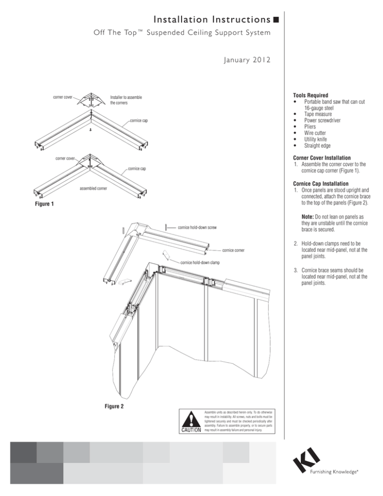
Inst a l l a t i o n I n st r u ct i o n s O ff Th e Top ™ Su s pended Ceiling S uppor t S ystem Januar y 2012 corner cover Tools Required • Portable band saw that can cut 16-gauge steel • Tape measure • Power screwdriver • Pliers • Wire cutter • Utility knife • Straight edge Installer to assemble the corners cornice cap Corner Cover Installation 1. Assemble the corner cover to the cornice cap corner (Figure 1). corner cover cornice cap Cornice Cap Installation 1. Once panels are stood upright and connected, attach the cornice brace to the top of the panels (Figure 2). assembled corner Figure 1 Note: Do not lean on panels as they are unstable until the cornice brace is secured. cornice hold-down screw cornice corner 2. Hold-down clamps need to be located near mid-panel, not at the panel joints. cornice hold-down clamp 3. Cornice brace seams should be located near mid-panel, not at the panel joints. Figure 2 Assemble units as described herein only. To do otherwise may result in instability. All screws, nuts and bolts must be tightened securely and must be checked periodically after assembly. Failure to assemble properly, or to secure parts may result in assembly failure and personal injury. Off The Top™ Ceiling Support System Installation Instructions Fairing Installation 1. Cut and screw the fairings to the top of the cornice cap using 49.0460 self-drilling screws (Figure 3). use 49-0460 to mount the fairings to the cornice cap corner cover fairing cornice cap cut and install the fairings to the top of the cornice cap Figure 3 Cross Support Installation 1. Cut and screw the support bars to the underside of the upper flange on the fairing using 49.0460 self-drilling screws spacing them 4’ - 0" apart (Figure 4). use 49-0460 to mount the support bars support bar “Off The Top” jack 2. Plan support bar location to avoid lights, HVAC, etc. 3. Maximum inside dimensions of office must be 12’ - 0" or less in one direction. cornice cap “Off The Top” jack install the support bars to the underside of the fairing Figure 4 2 Off The Top™ Ceiling Support System Installation Instructions L-channel (supplied by others) Suspended Ceiling Installation 1. Cut and screw ceiling trim edge to cornice brace around perimeter of inside of office using 49-0460 self-drilling screws (Figure 5). Be sure ceiling trim does not interfere with the removal of the shell. grid (supplied by others) support bar fairing 2. Install ceiling grid per manufacturer’s specifications. Support ceiling grid with wire between grid and support bar (Figure 5). 3. Install ceiling tile, lights, etc. per manufacturer’s specifications (Figure 6). “Off The Top” jack L-channel (supplied by others) wire (supplied by others) Install the L-channel around the perimeter of the cornice cap. Make sure the L-channel does not interfere with the removal of the panel shell. Install the T-bar main runners and attach to the support bars with wire. MAKE SURE TO AVOID ANY LIGHTS AND HVAC. Figure 5 fairing 49-0460 ceiling tile (supplied by others) support bar “Off The Top” jack wire (supplied by others) Figure 6 3 Off The Top™ Ceiling Support System Installation Instructions Cornice Cap Components 1. Refer to figure 7. 24" cornice cap (120") cornice corner cornice hold down screw cornice hold down clamp Figure 7 115” Fairing Components 1. Refer to figure 8. fairing 145.44” support bar 49.0460 self-drilling screws Off The Top jack corner cover splice Figure 8 Fairing Splice 1. Assemble the splice between the fairings (Figure 9). splice splice installer is to splice together the fairings if they do not match up assembled splice Guidelines • Maximum inside dimension of office must be 12’ - 0" or less in one direction (Figure 10). fairings • Space support bars 4’ - 0" apart. • Office walls with an inside dimension longer than 9’ - 0" require fairings to be cut and spliced (Figure 10). • This suspended ceiling support system is meant to support the ceiling and lighting system only and is not intended for heavy loads. Do not walk on support bars. • Follow the ceiling manufacturer’s recommendations for suspended ceiling. fairings Figure 9 unlimited office dimensions larger than 9'-0" require 2 or more fairings per office wall 12'-0" Max interior office size Figure 10 · · · · 1330 Bellevue Street P.O. Box 8100 Green Bay, WI 54308-8100 Tel 1-800-424-2432 www.ki.com · · © 2012 KI All Rights Reserved Litho in USA Code KI-61804R1/HT/GT/0112
