Initial verification
advertisement
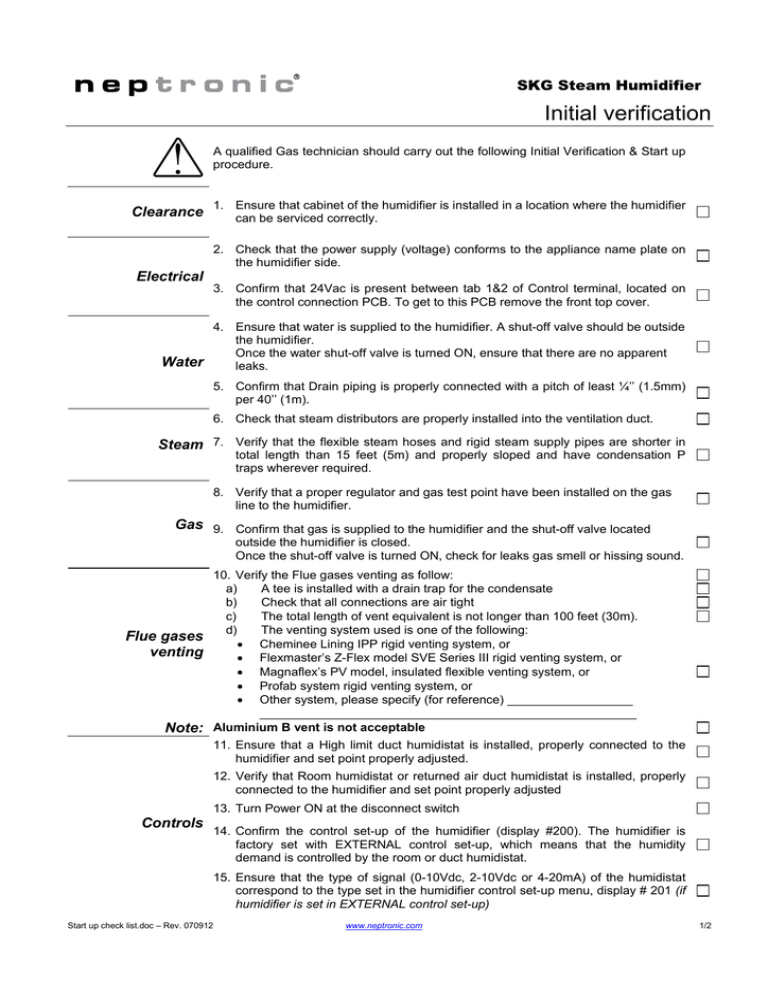
SKG Steam Humidifier Initial verification ! Clearance A qualified Gas technician should carry out the following Initial Verification & Start up procedure. 1. Ensure that cabinet of the humidifier is installed in a location where the humidifier can be serviced correctly. 2. Check that the power supply (voltage) conforms to the appliance name plate on the humidifier side. Electrical 3. Confirm that 24Vac is present between tab 1&2 of Control terminal, located on the control connection PCB. To get to this PCB remove the front top cover. 4. Ensure that water is supplied to the humidifier. A shut-off valve should be outside the humidifier. Once the water shut-off valve is turned ON, ensure that there are no apparent Water leaks. 5. Confirm that Drain piping is properly connected with a pitch of least ¼’’ (1.5mm) per 40’’ (1m). 6. Check that steam distributors are properly installed into the ventilation duct. Steam 7. Verify that the flexible steam hoses and rigid steam supply pipes are shorter in total length than 15 feet (5m) and properly sloped and have condensation P traps wherever required. 8. Verify that a proper regulator and gas test point have been installed on the gas line to the humidifier. Gas 9. Confirm that gas is supplied to the humidifier and the shut-off valve located outside the humidifier is closed. Once the shut-off valve is turned ON, check for leaks gas smell or hissing sound. 10. Verify the Flue gases venting as follow: a) A tee is installed with a drain trap for the condensate b) Check that all connections are air tight c) The total length of vent equivalent is not longer than 100 feet (30m). d) The venting system used is one of the following: Flue gases • Cheminee Lining IPP rigid venting system, or venting • Flexmaster’s Z-Flex model SVE Series III rigid venting system, or • Magnaflex’s PV model, insulated flexible venting system, or • Profab system rigid venting system, or • Other system, please specify (for reference) __________________ ______________________________________________________ Note: Aluminium B vent is not acceptable 11. Ensure that a High limit duct humidistat is installed, properly connected to the humidifier and set point properly adjusted. 12. Verify that Room humidistat or returned air duct humidistat is installed, properly connected to the humidifier and set point properly adjusted 13. Turn Power ON at the disconnect switch Controls 14. Confirm the control set-up of the humidifier (display #200). The humidifier is factory set with EXTERNAL control set-up, which means that the humidity demand is controlled by the room or duct humidistat. 15. Ensure that the type of signal (0-10Vdc, 2-10Vdc or 4-20mA) of the humidistat correspond to the type set in the humidifier control set-up menu, display # 201 (if humidifier is set in EXTERNAL control set-up) Start up check list.doc – Rev. 070912 www.neptronic.com 1/2 SKG Steam Humidifier Start-Up 1. Proceed to the start-up of the Humidifier, as follow: a) Open the front access door of the humidifier cabinet; make sure that manual drain valve is closed. b) c) d) Start-up e) f) g) Combustion field adjustment h) 2. 3. Check the location of the air flow switch in the system and its operation by stopping the fan (if possible). With no air movement in the air duct, the humidifier should automatically stop the combustion burner(s). 4. Turn the humidifier OFF, by pushing 5. Execute a manual drain, by pushing the (DRAIN) push button of the control panel. A water jet directed on the water level sensor located in the water level sight glass should start and create bubbles around it. Reset Air flow switch and humidistat(s) to the proper value, if needed. Humidifier is ready for normal operation. Safety test Drain and Reset End Start up the humidifier by pushing (ON/OFF) button located on the humidifier control panel. After 5 seconds, water will start to fill. Water level should slowly rise in the water level sight glass located on the side of the evaporation chamber. Verify that there is a humidity demand. Humidity demand is display on the humidifier LCD display. Humidifier LCD display will display the water level in percentage (%). When display is indicating water level at 100%, the water level in the water level sight glass should be approximately ¾’’ (20mm) below the safety belt band of the evaporation chamber. If there is a humidity demand, the burner combustion blower(s) will start, and after approximately 90 seconds the combustion will start. From a cold water start, the humidifier will require 5 to 10 minute prior steam production. Humidifier LCD display is indicating water temperature and flue gases temperature. During normal operation while steam is produced, the water temperature should be 212˚F (100˚C) and the flue gases temperature around 250 to 390˚F (120 to 200˚C). Water level percentage should not indicate less than 95%. Observe for water steam and flue gases leaks. Please refer to the Combustion field adjustment instructions enclosed in this package to perform this operation 6. 7. (ON/OFF) push button of the control panel. Water level sight glass Start up check list.doc – Rev. 070912 www.neptronic.com 2/2
