GPM Software Demo
advertisement

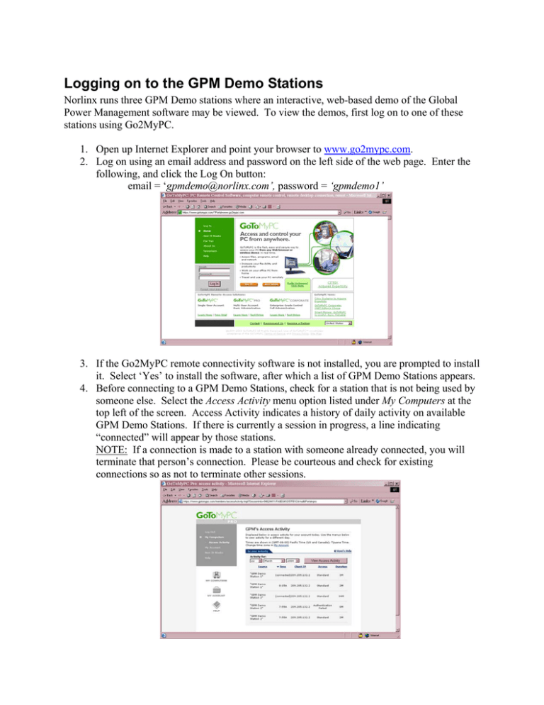
Logging on to the GPM Demo Stations Norlinx runs three GPM Demo stations where an interactive, web-based demo of the Global Power Management software may be viewed. To view the demos, first log on to one of these stations using Go2MyPC. 1. Open up Internet Explorer and point your browser to www.go2mypc.com. 2. Log on using an email address and password on the left side of the web page. Enter the following, and click the Log On button: email = ‘gpmdemo@norlinx.com’, password = ‘gpmdemo1’ 3. If the Go2MyPC remote connectivity software is not installed, you are prompted to install it. Select ‘Yes’ to install the software, after which a list of GPM Demo Stations appears. 4. Before connecting to a GPM Demo Stations, check for a station that is not being used by someone else. Select the Access Activity menu option listed under My Computers at the top left of the screen. Access Activity indicates a history of daily activity on available GPM Demo Stations. If there is currently a session in progress, a line indicating “connected” will appear by those stations. NOTE: If a connection is made to a station with someone already connected, you will terminate that person’s connection. Please be courteous and check for existing connections so as not to terminate other sessions. 5. Once you have checked for an existing connection, click the My Computers menu option or the My Computers icon located to the left of the screen for the list of GPM’s Computers. There are three GPM stations available. Click the Connect button beside the station of your choice. 6. During download of the GoToMyPC software, a message appears indicating it is initializing, downloading, and launching this process. When the software download is complete, the message indicates “Launch Successful.” 7. After the ‘Launch Successful’ message appears, a dialog box prompts for connecting to the GoToMyPC GPM Demo Stations (host computers). 8. You must enter the access code for the selected GPM Station in the next dialog box that appears. Enter the following, depending on the GPM station selected, and click OK: GPM Demo Station 1 – enter ‘gpmstation1’ GPM Demo Station 2 – enter ‘gpmstation2’ GPM Demo Station 3 – enter ‘gpmstation3’ 9. An Authentication dialog box appears to log on to the selected GPM Demo Station, followed by two dialog boxes indicating the appearance and initialization of the connection to the selected station. Starting Global Power Management Power Console After a brief pause, the connection appears full screen on your computer. The focus is placed on the desktop of the selected GPM Demo Station. The selected GPM Demo Station may already have the Global Power Management Power Console started. However, if the GPM Power Console is not open, access the program by selecting Start\All Programs\Power Console or Start\Programs\Startup\Powercon. NOTE: The GPM Demo Stations have been restricted to only allow execution of the GPM Power Console. All Other programs will produce an ‘Access Denied’ message. Once Power Console is launched, you may be prompted with a Global Power Management Login Screen or a message indicating the need to switch to Local Security and logon. If prompted, logon using Admin/Password for the UserID and Password. After you logon, you may maneuver within the web-based GPM Demo. There is lots to do and see, so enjoy! Global Power Management Software (GPM) Demo The Global Power Management (GPM) software provides an excellent user interface for viewing, managing, and controlling Baytech equipment. Once equipment is discovered and added to the GPM Power Management Console, this equipment can be organized into customized logical and functional views to easily perform the numerous functions and managerial tasks available within the software. Though numerous advanced features are available, this demonstration covers key highlights of Baytech’s solutions. You are encouraged to explore the software on the GPM Demo Stations to test drive its performance and power. Logical and Functional Organizations The views provided on the web-based GPM demo stations illustrate the core functions available with Baytech products through the GPM software. Explore these views as a starting point for creating your own organization’s structure within GPM to fit your needs. Baytech Equipment View Organizes existing equipment by network controller board followed by any existing module types as well as associated power strips. This view basically shows the types of equipment available for management. Facilities View This view is useful for showing Power Distribution Panels throughout a Data Center. A Power Distribution Panel may, for example, be divided into segments or cabinets, with associated power strips to each segment. Cabinet View This view shows power distribution that may exist across rows of cabinets in a Data Center. For example, the cabinets of a particular row may contain related servers or other equipment in which tracking of power distribution for like equipment is desired. These illustrate some of the common ways an organization may wish to group their equipment logically or functionally. GPM has the capability to create as many logical or functional views as an organization sees fit. The associated Baytech equipment that provides power to segments, cabinets, or other groups may be dragged and dropped into the assigned places. Once you have logged onto one of the GPM Demo Stations, click the Organizations drop-down list at the top to select a particular view. Note you can expand the folders and subfolders to the left in Tree View to see a list of Equipment. Use the divider bars in the middle to adjust viewing areas. Equipment is added by discovering controllers through the Controllers dialog box in GPM based upon the static IP address of the equipment. Status messages in the bottom yellow bar keep you informed of the process. When controllers are discovered, associated Power Strips and Outlets are pulled in and listed in the respective Controllers, Power Strips, and Outlets Panes at the bottom. Add new equipment to an existing group in the Tree View by using the familiar drag-and-drop method. Selecting equipment in Tree View also selects corresponding components in the bottom panes. Change the level in Tree View by selecting the drop-down for Expand/Contract at the top to maneuver to the desired level. Any number of organizations, groups, and subgroups may be created, and equipment organized using a drag-and-drop method to accommodate your organization. Switch between views by using the Organizations drop-down list or the Find Organization Node button, showing GPM’s advanced ability to maintain existing configuration schemes through its easy-to-use GUI. You can customize organization, group, subgroup, and equipment names by renaming them to fit your company’s needs. Whenever a function requires information, you are prompted with a dialog box for the information. All objects, whether a piece of equipment or a folder in Tree View may be renamed. Right click an item and select rename to see this feature. Linked Outlets When the outlets of a power strip are split in assignment across groups in Tree View, a linked power strip is created. Creating linked outlets of a power strip and using power sequencing to control On, Off, and Reboot functions is useful for devices with multiple receptacles. A folder icon changes to a linked outlet group icon whenever a power strip or outlet is dropped into a selected folder. As an example, click the Organizations drop-down list and select the Cabinet View. Notice the last group called “Linked Group” containing outlets pulled from different Power Strips. GPM allows the sequence of On and Off functions in any order for a linked power strip containing linked outlets. Delays in seconds control when these functions occur. Such management is useful for bringing up device power supplies in a desired sequence, and as a great Contingency Data Management Plan for such occurrences as brown outs. Click on the Power Sequence tab in the Information Pane. All outlets of the linked power strip appear in the lists for On and Off functions. You can change the order of sequencing for the outlets, as well as the delay on the Power Sequence tab. Right clicking an item in Tree View or under one of the bottom panes displays a list of available functions for that particular item. Functions for controllers, power strips, and outlets are the same selected in the panes at the bottom in Tree View, but will vary depending upon which item is selected. In this manner, GPM provides management for all objects within the software. As an example, select a controller from the Controllers Pane at the bottom, then right click one of its associated power strips. You can turn off, turn on, or reboot the entire Power Strip. Capturing Power GPM offers a number of ways to capture and display information concerning power across multiple entities. You can view graphical displays of power information by selecting an entire Controller, a single Power Strip, or a single Outlet. The Status tab displays summary information for whichever item is selected, and polls using the settings on GPM Setup’s Polling tab to receive updated information. Alerts are recorded in case any of the alarms are tripped for any of the equipment. Reporting features are also available. Click the Organizations drop-down list, and select the Facilities View. Expand the Norlinx group to view Segment E. Click on the Controller or Power Strip, and click the Power Sequence tab. Notice the graphical information displayed for that device in terms of Voltage, Amps, Watts, and Temperature if the equipment has these capabilities. Right click the selected Controller or Power Strip from the bottom panes, and select Setup. Make sure the Power Strip tab is selected. Note the threshold values and the ability to set each value. Based upon these settings, Alerts are collected if triggered by threshold violations. Click in the text box for the Temperature setting, and enter the value ’50.’ Click the Alarm button to the left of the text box, and click the Controller tab. Click the Trap Setup button, and make sure the Over Temperature Violation box has ‘Y’ for the Log column value. Click the Save button, click Yes to save settings, and then the Exit button. Click Done Selecting, and then close the Controller Setup/Status dialog box. Click the Alerts tab, and notice the alerts appear for violation of Temperature. GPM has the capability to display a number of alerts, including alerts through email and sound. GPM also functions as a reporting tool for textual and graphical information. To see this feature, click the Reports menu at the top. You can generate reports from any level in Tree View and include all or selected items in Tree View. Choose an item in Tree View, and leave Reports set on Graphs. Check all available options for Power, Voltage, Current, Max. Current, and Temp at the bottom right of this screen. Double click the Immediate Results tab. Notice your selected options are polled and information is displayed. Information can be refreshed by clicking the Refresh button. The Capture tab may be used to capture information on selected equipment over a specific time period for graphical displays. Click the Capture tab, and set the interval for Seconds to 45 by using the up and down arrows. Click the Run button, and the capture begins. GPM counts down 45 seconds as it records information, and then updates the tabs to the left with the recorded information. The cycle continues counting and updating every 45 seconds. Click the red stop button and click Yes to end the recording session, and click any of the available tabs to the left display graphical summaries of information. Close the Reports window when done. Security GPM has the capability of implementing local or network-based security for equipment controlled by the GPM software. The three possible security modes in GPM are Local, WinNT, and None. Local implements security with local accounts that are created and given respective rights, while WinNT allows importing accounts from a Primary Domain Controller (PDC) or Win2000 network server (Active Directory) and then assigning necessary rights. None turns off all security and permissions within GPM. The security type is set on GPM Setup’s Security tab. Additional options, such as hiding tree nodes from unauthorized users and filtering for particular domain names or tree nodes provides extra power to a network-based environment for monitoring rights and access to Baytech equipment. The demos on the GPM stations have been placed on WinNT Security in order to see security features. Once configured, users and groups are created internally (if Local Security Type is selected) or externally pulled from Windows NT Domains/Windows 2000 Active Directory (WinNT Security Type), and then assigned any necessary permissions to logical organizations. Even though WinNT security is used with the demos, local security may also be chosen. The only difference between the two is that local security creates local accounts and permissions, whereas WinNT security pulls existing users and groups in from a Primary Domain Controller or Windows 2000 Active Directory structure. Whether users and groups are pulled in or created locally, existing equipment, groups, and subgroups are assigned users and groups using the common drag-and-drop method. The Security tab in the GPM Console always displays assigned users and groups to an item when selected in Tree View. If local security is being used, users and groups are created via GPM Setup’s Access Local Security Setup button on the Security tab. Note this feature is also useful because it allows network administrators to perform account maintenance when the PDC or server with Active Directory is down. As an example of WinNT security, select the Facilities View in the GPM demo using the Organizations drop-down list at the top. Expand the Norlinx – Raleigh – Data Center folder in Tree View, and click the topmost level. Click the Security tab to the right, and click the key icon at the top. Notice the existing network users and groups are pulled in and displayed in the pane to the right. Expand Users and Groups to see those available, and click back on the folders in Tree View. GPM allows assigning specific users and groups to equipment by dragging from the users and groups to the right and dropping onto selected items in Tree View on the left. Summary information of rights and permissions is displayed in the middle on the Security tab. Click other groups in Tree View to see other assigned users and groups. Assigned Users and Groups are also displayed under Inherited when clicking equipment in the bottom panes. Once users and groups have been assigned to existing items in Tree View, functions performed by that user or group may be set up. To do this, simply right click a user or group from the listing in the Security pane. A list of available functions appears. Select the desired functions by clicking the box in front of a function, and click Done when all selections have been made. Users and groups will be limited to the selected functions whenever they log on, whether as a local account or a network-based account. Close the Security Structure to the right when done. Disconnecting from the Demos To disconnect from a GPM Demo Station, simply click the File menu and select Disconnect at the top of the GoToMyPC screen. You will be prompted with a Confirm Quit dialog box. Select Yes to Quit and the GPM Demo session window will close.


