Pipe Sizing Layout - The Urban Farmer Store
advertisement
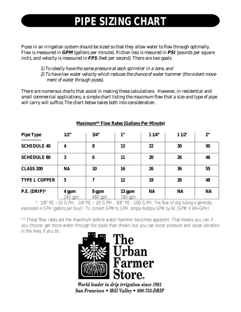
PIPE SIZING CHART Pipes in an irrigation system should be sized so that they allow water to flow through optimally. Flow is measured in GPM (gallons per minute), friction loss is mesured in PSI (pounds per square inch), and velocity is measured in FPS (feet per second). There are two goals: 1) To ideally have the same pressure at each sprinkler in a zone, and 2) To have low water velocity which reduces the chance of water hammer (the violent movement of water through pipes). There are numerous charts that assist in making these calculations. However, in residential and small commercial applications, a simple chart listing the maximum flow that a size and type of pipe will carry will suffice. The chart below takes both into consideration. Maximum** Flow Rates (Gallons Per Minute) Pipe Type 1/2” 3/4” 1” 1 1/4” 1 1/2’ 2” SCHEDULE 40 4 8 13 22 30 50 SCHEDULE 80 3 6 11 20 26 46 CLASS 200 NA 10 16 26 36 55 TYPE L COPPER 5 7 12 19 26 48 P.E. (DRIP)* 4 gpm 8 gpm 13 gpm NA NA NA 240 gph 480 gph 780 gph * 1/8” P.E. –10 G.P.H., 1/4”P.E. – 20 G.P.H., 3/8” P.E. –100 G.P.H. The flow of drip tubing is generally expressed in GPH (gallons per hour). To convert GPM to GPH, simply multiply GPM by 60. (GPM X 60=GPH) ** These flow rates are the maximum before water hammer becomes apparent. That means you can, if you choose, get more water through the pipes than shown, but you can loose pressure and cause vibration in the lines, if you do.
