Clifford of Vermont Gel-Filled Traffic Signal Cable
advertisement
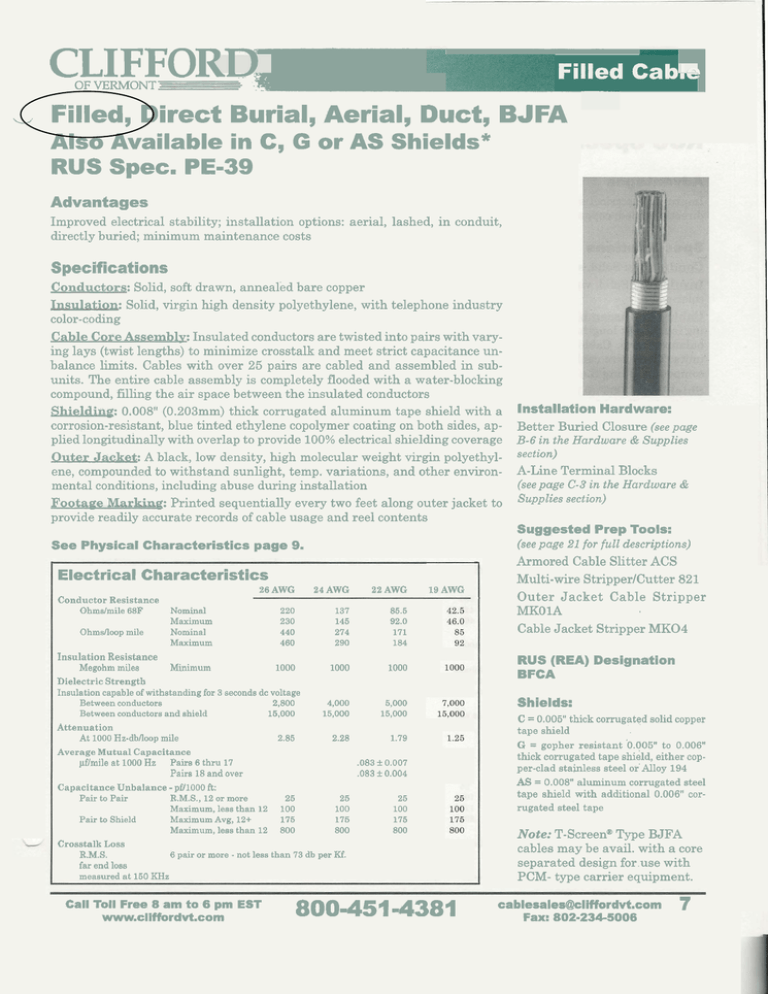
C L OF VERMONT L I F F O R O Filled Cab,, Filled, Direct Burial, Aerial, Duct, BJFA rn Also Available in C, G or AS Shields* RUS Spec. PE-39 Advantages Improved electrical stability; installation options: aerial, lashed, in conduit, directly buried; minimum maintenance costs Specifications Conductors: Solid, soft drawn, annealed bare copper Insulation: Solid, virgin high density polyethylene, with telephone industry color-coding Cable Core Assemblv: Insulated conductors are twisted into pairs with varying lays (twist lengths) to minimize crosstalk and meet strict capacitance unbalance limits. Cables with over 25 pairs are cabled and assembled in subunits. The entire cable assembly is completely flooded with a water-blocking compound, filling the air space between the insulated conductors Shielding: 0.008" (0.203mm) thick corrugated aluminum tape shield with a corrosion-resistant, blue tinted ethylene copolymer coating on both sides, applied longitudinally with overlap to provide 100%electrical shielding coverage Outer Jacket: A black, low density, high molecular weight virgin polyethylene, compounded to withstand sunlight, temp. variations, and other environmental conditions, including abuse during installation F o o t a ~ Marking: e Printed sequentially every two feet along outer jacket to provide readily accurate records of cable usage and reel contents See Physical Characteristics page 9. Electrical Characteristics Conductor Resistance Ohms/mile 68F O h m d w p mile 26AWG 24AWG 22AWG 220 230 440 460 137 145 274 290 85.5 92.0 171 184 Nominal Maximum Nominal Maximum 19 AWG Insulation Resistance Megohm miles Minimum 1000 1000 1000 Dielectric Strength Insulation capable of withstanding for 3 seconds dc voltage Between conductors 2,800 4,000 5,000 Between conductors and shield 15,000 15,000 15,000 Attenuation At 1000 Hz-dbnoop mile 2.85 2.28 1.79 Average Mutual Capacitance @mile a t 1000 Hz Pairs 6 thru 17 ,083 f 0.007 Pairs 18 and over .083 rt 0.004 Capacitance Unbalance - pf11000 ft: Pair to Pair R.M.S., 12 or more 25 25 25 Maximum, less than 12 100 100 100 Pair to Shield Maximum Avg, 12+ 175 175 175 Maximum, less than 12 800 800 800 Crosstalk Loss R.M.S. 6 pair or more - not less than 73 db per Kf. far end loss measured a t 150 KHz Call Toll Free 8 am to 6 pm EST www.cliffordvt.com 8004514381 Installation Hardware: Better Buried Closure (see page B-6 in the Hardware & Supplies section) A-Line Terminal Blocks (see page C-3 in the Hardware & Supplies section) Suggested Prep Tools: (see page 21 for full descriptions) Armored Cable Slitter ACS Multi-wire StripperICutter 821 Outer Jacket Cable Stripper MKOlA Cable Jacket Stripper MK04 RUS (REA) Designation BFCA Shields: C = 0.006" thick corrugated solid copper t a p e shield G = gopher r e s i s t a n t '0.005"t o 0.006" thick corrugated t a p e shield, e i t h e r copper-clad stainless steel or' Alloy 194 AS = 0.008" a l u m i n u m corrugated steel t a p e shield w i t h additional 0.006" corr u g a t e d steel t a p e Note: T-Screene Type BJFA cables may be avail. with a core separated design for use with PCM- type carrier equipment. cablesale~liffordvt.com Fax: 802-234-5006 7 Filled Cable Filled, Direct Burial, Aerial, Duct, BJFC RUS Spec. PE-39 Advantages Improved electrical stability; installation options: aerial, lashed, in conduit, directly buried; copper tape shielding; minimum maintenance costs Specifications Conductors: Solid, soft drawn, annealed bare copper Insulation: Solid, virgin high density polyethylene, with telephone industry color-coding Cable Core Assemblv: Insulated conductors are twisted into pairs with varying lays (twist lengths) to minimize crosstalk and meet strict capacitance unbalance limits. Cables with over 25 pairs are cabled and assembled in subunits. The entire cable assembly is completely flooded with a water-blocking compound, filling the air space between the insulated conductors. Shielding: 0.005" (0.127mm) thick corrugated solid copper tape shield applied longitudinally with overlap to provide 100%electrical shielding coverage Outer Jacket: A black, low density, high molecular weight virgin polyethylene, compounded to withstand sunlight, temperature variations, and other environmental conditions, including abuse during installation Footape Marking: Printed sequentially every two feet along the outer jacket to provide readily accurate records of cable usage and reel contents Installa*ion Hardware: Better Buried Splice Closure (see page B-6 in the Hardware & Supplies section) Electrical Characteristics Conductor Resistance Ohmslmile 68F Ohmsnoop mile 26AWG 24AWG 22AWG 19AWG 220 230 440 460 137 145 274 290 85.5 92.0 171 184 42.5 46.0 85 92 1000 1000 1000 Nominal Maximum Nominal Maximum Insulation Resistance Megohm miles Minimum 1000 Dielectric Strength Insulation capable of withstanding for 3 seconds dc voltage 2,800 Between conductors Between conductors and shield 15,000 Attenuation At 1000 Hz-dbfloopmile Average Mutual Capacitance @mile at 1000 Hz Pairs 6 thru 17 Pairs 18 and over 2.85 4,000 15,000 5,000 15,000 7,000 15,000 2.28 1.79 1.25 25 100 175 800 25 100 175 800 25 100 175 800 Crosstalk Loss 6 pair or more not less than 73 db per K€. R.M.S. far end loss measured at 150 KHz - 8 Call Toll Free 8 am to 6 pm EST www.cllffordvt.com (see page 21 for full deqcriptions) Armored Cable Slitter ACS Outer Jacket Cable Stripper MKO 1A Cable Jacket Stripier MK04 .083 rt 0.007 ,083 rt 0.004 25 100 175 800 page C-3 in the Hardware & Supplies section) Metal Pedestals (seepage 23-5in the Hardware & Supplies section) Suggested Prep Tools: - Capacitance Unbalance pi71000 ft: Pair to Pair R.M.S., 12 or more Maximum, less than 12 Pair to Shield Maximum Avg, 12+ Maximum, less than 12 A-Line Terminal Blocks (see 8004514381 RUS (REA) Designation BFCC Note: T-ScreenmType BJFC cables may be avail. with a core separated design for use with PCM- type carrier equipment. cablesales@cliffordvt.com Fax: 802-234-5006 .Y *Standard stocking items. Other items may be available upon request. Physical Characteristics No. Pairs - 24 AWG Filled BJFA, BJFC, PE-39 Conductor Size: 0.0201"(0.51 mm) Insulation Thickness: 0.012"(0.30mm) 22 AWG = Filled BJFA, BJFC, PE-39 Conductor Size: 0.0254" (0.64mm) Insulation Thickness: 0.015" (0.39mm) Conductor Size: 0.0359" (0.91mm) Insulation Thickness: 0.021" (0.52mm) Jacket Thickness inch m m Outside Diameter inch m m Approx. Shipping Weight 1bslK-ft. kglkm Standard Reel Length Feet Meters *6 *12 18 *25 *50 *75 *loo *I50 *200 *300 *400 *600 900 1200 1500 1800 *6 *12 18 *25 *50 75 *loo 150 200 300 400 600 900 1200 - 1 9 AWG Filled BJFA, BJFC, PE-39 Clifford Part Number *6 *12 *18 "25 *50 75 100 150 200 300 400 26 AWG Filled BJFA, BJFC, PE-39 always available upon request. Conductor size: 0.0159" (0.40 mm) - Insulation thickness: 0.010'' (0.24 mm) u Call Toll Free 8 am to 6 pm EST www.cliffordvt.com 800-451-4381 cablesales@cliffordvt.com Fax: 802-234-5006 9

