1-turn Contactless potentiometer
advertisement

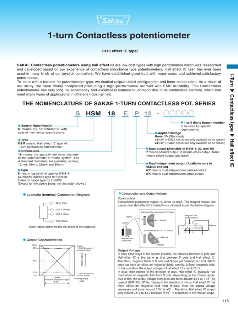
1-turn Contactless potentiometer (Hall effect IC type) ▼ 1-Turn SAKAE Contactless potentiometers using hall effect IC are low-cost types with high performance which was researched and developed based on our experience of contactless inductance type potentiometers. Hall effect IC itself has ever been used in many kinds of our joystick controllers. We have established great trust with many users and achieved satisfactory performance. To meet with a request for potentiometer type, we studied unique circuit configuration and inner construction. As a result of our study, we have finally completed producing a high-performance product with EMS durability. The Contactless potentiometer has very long life expectancy and excellent resistance to vibration due to its contactless element, which can meet many types of applications in different industrial field. S HSM 18 E P 12 - ○○○○○ ● 4 or 5 digits branch number to be used for specific requirements. ● Applied Voltage None: 5V (Standard) ● Special Specification S means the potentiometer with special mechanical specifications. HSM means Hall effect IC type of 1-turn contactless potentiometer. ● Dimensions 18 means the approximate outer diameter of the potentiometer in metric system. The 4 standard diameters are available, namely, 12mm, 18mm, 22mm and 30mm. ● Dual output (Available in HSM18, 22, and 30) P means parallel output. X means cross output. None means single output (standard) ● Dual independent output (Available only in HSM22 and 30) WP means dual independent parallel output WX means dual independent cross output ● Type E means lug terminal type for HSM18 EL means leadwire type for HSM18 F means flange type for HSM30 (Except for the above types, no character shows.) ● Leadwire (terminal) Connection Diagram ● Construction and Output Voltage Construction Semicylinder permanent magnet is joined to shaft. The magnet rotates and passes near Hall effect IC installed in circuit board as per the below diagram. IN 5V (Red) OUT A (White) Shaft stays at the neutral position.(2.5V output) OUT B (Blue) Hall IC Magnetic field (Magnetic flux) S Magnet GND (Black) Magnet N Voltage Note: Above colors means the colors of the leadwires Current Shaft rotates itself by + 45°(4.5V output) Diagram from a side view ● Output Characteristics 100% OUT A (OUT B In case of a parallel output) 90% Output Voltage 50% 10% (OUT B in case of a cross output) 0% Center Effective Electrical Angle ±45° Rotating Angle →CW S Magnet N + Rotation Output Voltage In case shaft stays at the neutral position, the distance between S pole and Hall effect IC is the same as that between N pole and Hall effect IC. Therefore, magnetic fields of S pole and N pole get balanced out and Hall IC does not have an effect on magnetic fields, namely, 0(Zero) magnetic field. In this condition, the output voltage of Hall effect IC is set to 2.5V. In case shaft rotates in the direction of plus, Hall effect IC gradually has more effect on magnetic field from S pole depending on the rotation angle. Due to this, the output voltage increases and turns around 4.5V at + 45°(in case of HSM18E). While, rotating in the direction of minus, Hall effect IC has more effect on magnetic field from N pole, then the output voltage decreases and turns around 0.5V at -45° . Therefore, Hall effect IC output gets around 0.5 V to 4.5V between ±45°in proportion to the rotation angle. 115 1 Hall effect IC 12:12V (HSM22 and 30 are only available as an option.) 24:24V (HSM22 and 30 are only available as an option.) ● Type ▼ Contactless type THE NOMENCLATURE OF SAKAE 1-TURN CONTACTLESS POT. SERIES


