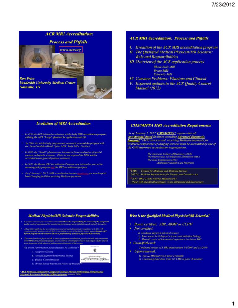
7/23/2012 ACR MRI Accreditation: Process and Pitfalls
advertisement

7/23/2012 ACR MRI Accreditation: Process and Pitfalls www.acr.org ACR MRI Accreditation: Process and Pitfalls I. Evolution of the ACR MRI accreditation program II. The Qualified Medical Physicist/MR Scientist: Role and Responsibilities III. Overview of the ACR application process Whole-body MRI Breast MRI Extremity MRI Ron Price Vanderbilt University Medical Center Nashville, TN Evolution of MRI Accreditation • In 1996 the ACR initiated a voluntary whole-body MRI accreditation program utilizing the ACR “Large” phantom for application and QA • In 2008, the whole-body program was converted to a modular program with six clinical modules (Head, Spine, MSK, Body, MRA, Cardiac) IV. Common Problems: Phantom and Clinical V. Expected updates to the ACR Quality Control Manual (2012) CMS/MIPPA MRI Accreditation Requirements As of January 1, 2012, CMS/MIPPA* requires that all non-hospital based facilities providing Advanced Diagnostic Imaging** (ADI) services and receiving Medicare payments for technical components of imaging services must be accredited by one of the CMS-approved accreditation organizations. • In 2008, the “Small” phantom was introduced for accreditation of special purpose orthopedic scanners. (Note: Is not required for MSK module accreditation on general purpose scanners) The American College of Radiology (ACR) The Intersocietal Accreditation Commission (IAC) The Joint Commission (TJC) (Ambulatory Health Care Program) • In 2010, the Breast MRI Accreditation Program was initiated as part of the mammography program not the MRI accreditation program • As of January 1, 2012, MRI accreditation became mandatory for non-hospital based imaging facilities receiving Medicare payments. *CMS: Centers for Medicare and Medicaid Services MIPPA: Medicare Improvements for Patients and Providers Act **ADI: MRI, CT and Nuclear Medicine/PET (Note: ADI specifically excludes: x-ray, ultrasound and fluoroscopy) Medical Physicist/MR Scientist Responsibilities • A qualified medical physicist/MR scientist must have the responsibility for overseeing the equipment quality control program and for monitoring performance upon installation and routinely thereafter. • All facilities applying for accreditation or renewal must demonstrate compliance with the ACR requirements for quality control (QC) by including a copy of the facility’s most recent Annual MRI System Performance Evaluation (must be performed by a medical physicist/MR scientist). • The annual medical physicist/MR scientist performance evaluation just also include and assessment of the MRI safety program (signage, access control, screening procedures and oxygen safety) as well as an inspection of the physical and mechanical integrity of the system. MR System Performance Characteristics to be Monitored* A. Acceptance Testing B. Annual Equipment Performance Testing C. Quality Control Program Who is the Qualified Medical Physicist/MR Scientist? • Board certified: ABR, ABMP or CCPM • Not certified: 1) Graduate degree in physical science 2) Two courses in biological sciences and radiation biology 3) Three (3) years of documented experience in clinical MRI • Grandfathered: Conducted surveys of 3 MRI units between 1/1/2007 and 1/1/2010 • Upon renewal: 1) Two (2) MRI surveys in prior 24 months 2) Continuing Education Units (15 CME in prior 36 months) D. Written Survey Reports and Follow-up Procedures *ACR Technical Standard for Diagnostic Medical Physics Performance Monitoring of Magnetic Resonance Imaging (MRI) Equipment (revised 2009) 1 7/23/2012 For non-hospital based facilities, which modalities have been designated by the Centers for Medicare and Medicaid Services (CMS) as “Advanced Diagnostic Imaging” services and thus, must be accredited by 1/1/2012. The Role of the Medical Physicist 1) The MRI team: physician, technologist, administrator and physicist 2) You are the primary resource for: pulse sequences acquisition parameters system performance artifacts safety review and adequacy of submitted DICOM images changes in accreditation instructions and requirements 0% 0% 0% 3) Yes, you should determine that the system performance meets the ACR guidelines but more importantly, you should determine if the system meets your expectations based on your own knowledge and experience, e.g. a 1.5T system that has a LCD score of 9, can pass accreditation but is clearly not functioning properly. 0% 0% 1. 2. 3. 4. 5. MRI, CT and Ultrasound MRI, Nuclear Medicine/PET and CT MRI, Ultrasound and Fluoroscopy MRI, Fluoroscopy and CT MRI, Ultrasound and Nuclear Medicine/PET 10 For non-hospital based facilities, which modalities have been designated by the Centers for Medicare and Medicaid Services (CMS) as “Advanced Diagnostic Imaging” services and thus, must be accredited by 1/1/2012? 1. 2. 3. 4. 5. MRI, CT and Ultrasound MRI, Nuclear Medicine/PET and CT MRI, Ultrasound and Fluoroscopy MRI, Fluoroscopy and CT MRI, Ultrasound and Nuclear Medicine/PET Phase 1: “Entry Application” (Must be completed online.) Phase 2: “Full Application” You will then receive a Testing Material Packet for the Full Application. Please note that within the year (2012) the full application submission will also be available online. For the whole-body and extremity magnets the Full Application requires: • Phantom and Clinical Images • Equipment Performance Report for each magnet (< 1 year) and last quarter QC documents #1 https://acredit.acr.org/ The accreditation process consists of two phases: Essentially to request a Testing Material Packet for the Full Application Reference: Center for Medicare and Medicaid Services website http://www.cms.gov/Medicare/Provider-Enrollment-andCertification/MedicareProviderSupEnroll/AdvancedDiagnosticImagingAccreditati on.html Online Application ACR Accreditation Application Overview Note: At the present time the Breast MRI application does not require phantom images but does require the Physicist’s Equipment Performance Report and QC documents. ACR MR Accreditation Phantoms Manufacturer: J.M Specialty Parts 11689-Q Sorrento Valley Rd San Diego, CA 92121 (619) 794-7200 #2 Three Sections * *Date of last equipment evaluation/physics survey. “large phantom” “small phantom” #3 2 7/23/2012 Phantom Site Scanning Instructions Phantom Image Data Phantom images must be submitted on DICOM CD-ROM format CD must contain all five phantom imaging sequences for both large and small phantoms: 1) Sagittal localizer (TE/TR = 20/200 msec) 2) ACR T1-weighted sequence (TE/TR = 20/500 msec) 3) ACR T2-weighted Sequence (TE/TR = 20-80/2000 msec) 4) Site T1-weighted sequence and 5) Site T2-weighted sequence CD should not include an embedded viewer . ACR Phantom Data Forms Large Phantom FOV = 25 cm 256X256 11 slices: 5mm @ 5 mm gap Small Phantom Scan #1: ACR Sagittal Localizer (SE 20/200 ms, FOV = 25 cm, 256X256, slice = 20 mm, NEX = 1, Time = 0.56 s) FOV = 12 cm 152X192 7 slices: 5mm @ 3 mm gap Accurate 3D alignment is essential! Scan #2: ACR Axial T1 ACR (large) Phantom Analysis Scan #3: ACR Axial Dual Echo T2 ( Note: Also typically used for weekly QC Measurements.) (SE 20-80/2000 ms, 25 cm, 256X256, multi-slice (11 at 5mm), 1 NEX, Time = 8:56 min) #1 #5 #9 #7 #8 #10 #11 #1) Slice thickness and position, geometric accuracy, high contrast resolution Compliments of Ed Jackson, PH.D. #5) Geometric accuracy #7) Percent image uniformity, ghosting #8-11) Low contrast object detectability, and slice position (in #11) Slide courtesy of E.F. Jackson, PhD 3 7/23/2012 ACR (small) Phantom Large phantom - Geometric Accuracy #1 Sag Loc Sag localizer: Geometric accuracy #1) Slice thickness and position, geometric accuracy, high contrast resolution #3) Geometric accuracy #5) PIU, ghosting #6-7) LCD #3 #6 #5 #7 1 sag 20 mm slice 7 axial 5mm slices w/ 3mm gap Slice 1 Sag Loc Slice 5 Criteria: 190 ± 2 mm Criteria: 148 ± 2 mm FOV 12 cm 192 x 152 matrix Five Sequences 1) ACR Sagittal (20/200) 4) Site T1 2) ACR T1 SE (20/500) 5) Site T2 3) ACR T2 SE (80/2000) ACR Guidelines for Phantom Scans Small phantom - Geometric Accuracy Large Phantom (FOV = 25 cm, 256X256) Dimensional accuracy (Sagittal) Dimensional accuracy (Axial) Slice Thickness Slice Position Image Uniformity (PIU) Percent Signal Ghosting High-contrast Resolution Low-contrast Detectability Score 148 ± 2 mm 190 ± 2 mm 5 ± 0.7 mm ≤ 5mm ≥ 87.5% (< 3T) ≥ 82.0% (3T) ≤ 2.5% 1 mm ≥ 9 (<3T) ≥ 37 (3T) Small Phantom (FOV = 12 cm, 152X192) Slice 1 Slice 3 Dimensional accuracy (Sagittal) Dimensional accuracy (Axial) Slice Thickness Slice Position Image Uniformity (PIU) Percent Signal Ghosting High-contrast Resolution Low-contrast Detectability Score Sag Loc Criteria: 100 ± 2 mm 100 ± 2 mm 100 ± 2 mm 5 ± 0.7 mm ≤ 5mm ≥ 87.5% (< 3T) ≤ 2.5% 0.8 mm ≥ 9 (<3T) ACR Phantom Test Guidance Documents Instructions for: • How to evaluate images using DICOM viewer (Kpacs , ClearCanvas, Osiris/Osirix) • Performance criteria that must be met by each unit • Common reasons for failure • Sent to site with Full Application packet • Also available at ACR website What are the ACR phantom performance guidelines for the percent image uniformity (PIU) and low-contrast detectability (LCD) for 3T and 1.5T systems, respectively? 0% 1. 0% 2. 0% 0% 3. 0% 4. PIU=87.5%(3T) and 82%(1.5T), and LCD guidelines are the same PIU guidelines are the same, and LCD = 37(3T) and 9(1.5T) PIU= 87.5% (3T) and 82%(1.5T), and LCD = 37 (3T) and 9 (1.5T) PIU= 82%(3T) and 87.5%(1.5T), and LCD 37(3T) and 9(1.5T) 10 4 7/23/2012 Common Phantom Image Failures What are the ACR phantom performance guidelines for the percent image uniformity (PIU) and low-contrast detectability (LCD) for 3T and 1.5T systems, respectively? 1. 2. 1. PIU=87.5%(3T) and 82%(1.5T), and LCD guidelines are the same 2. PIU guidelines are the same, and LCD = 37(3T) and 9(1.5T) 3. PIU= 87.5% (3T) and 82%(1.5T), and LCD = 37 (3T) and 9 (1.5T) 4. PIU= 82%(3T) and 87.5%(1.5T), and LCD 37(3T) and 9(1.5T) 3. 4. 5. Reference: ACR website www.acr.org http://www.acr.org/~/media/ACR/Documents/Accreditation/MRI/LargePhantomGuidance.pdf http://www.acr.org/~/media/ACR/Documents/Accreditation/MRI/SmallPhantomGuidance.pdf 6. Poor phantom alignment a. Low-contrast detectability (LCD insert miss-alignment) b. Slice-thickness (ramps rotated with respect to slice) c. Slice position accuracy (laser alignment or gradient calibration) Ghosting/Artifacts (gradient instability, motion, eddy currents, narrow BW, etc) a. Interference with LCD spokes b. RF leaks and others leading to “Unacceptable Artifacts” designation Signal-to-Noise (<1.5T as well as 3T) a. Low-field: LCD score < 9 b. High-field (3T): LCD score < 37 Gradient non-linearity (uncorrected)/B0 inhomogeneity (poor magnet shim) a. Geometric distortion b. Dimensional accuracy Array coil based failures (non-function element or no image intensity correction) a. Percent Image Uniformity (PIU) failure b. Image intensity correction not used Other: Incorrect sequence parameters: FSE vs SE, Half Fourier, acceleration (SENSE, GRAPPA, etc), excessive filtering, narrow BW distortions or combined effects Poor Phantom Positioning LCD Insert miss-alignment Ghosting/Artifacts/Spatial Distortion Rotation Right-to-Left Ghosting Gradient Calibration May affect slice thickness calculation, low-contrast detectability, as well as dimensional measurements. Slice thickness miss-alignment Rotation Anterior-Posterior RF Bo Inhomogeneity LCD Failure SNR: Low-Contrast Detectability 8-Channel Coil 0.3 T Slice #11 LCD Score = 12 No image Intensity Correction: Multi-element Coils (SCIC, CLEAR, PURE, …) LCD Score = 6 PIU = 76% 3T Slice #8 LCD Score = 39 LCD Score = 34 5 7/23/2012 Common Clinical Image Failure • Unacceptable acquisition parameters • Each Clinical Module has specific technical requirements. • The Medical Physicist should review the DICOM header information to confirm appropriate acquisition parameters prior to submission. At the present time there is no specific ACR MRI phantom. For Breast MRI Accreditation, the Medical Physicist/MR Scientist has the added responsibility of choosing the phantom to be used for the weekly QA measurements and determining the specifics of the QC program. Currently, the ACR Breast MRI Accreditation application does not require phantom images. www.acr.org However because of the specific and detailed requirements for the clinical image acquisition parameters, the Medical Physicist has an important roll in the submission process to confirm that the images meet the technical requirements. Breast Weekly QC Options The Medical Physicist will need to review the DICOM header information for the site to confirm that the images meet the ACR quidelines, e.g. slice thickness, phase and frequency-encoding steps, FOV and image acquisition time. Common Clinical Image Problems in Breast MRI Accreditation. 1) 2) 3) 4) 5) Incorrect acquisitions parameters (pixel > 1 mm, slice > 3 mm or gaps > 0 mm) Poor fat suppression or no pre-post contrast subtraction images Interpolated images Poor Position of breast within coil (skin folds) Artifacts (truncation, wrap (slice and phase), motion, … Out-of Volume Slice wrap-around Skin folds Non-uniform fat suppression Phase-encode direction Cardiac Motion Note: this is the correct PE direction to avoid breast overlap. Out-of plane interference Slice= 1.6i (interpolated) 6 7/23/2012 In regard to ACR Breast MRI accreditation, only one of the following is correct? In regard to ACR Breast MRI accreditation, only one of the following is correct? 1. 2. 3. 4. 0% 0% 0% 0% 5. 0% The MRI system must be a dedicated breast facility Routine QA does not require the use of a phantom The MRI field strength must be at least 1.5T No phantom images are required as part of the accreditation application The use of a bilateral coil is optional 1. The MRI system must be a dedicated breast facility 2. Routine QA does not require the use of a phantom 3. The MRI field strength must be at least 1.5T 4. No phantom images are required as part of the accreditation application 5. The use of a bilateral coil is optional Reference: ACR website www.acr.org 10 Anticipated Changes in the ACR MRI Quality Control Manual (Revision expected 2012) http://www.acr.org/~/media/ACR/Documents/Accreditation/BreastMRI/Requirements.pdf ACR Annual Performance Report Measurements, ct’d 1. 2. 3. 4. (Note: Changes have yet to be approved) 1. 2. 3. 4. Annual Physics Report must include verification of technologist weekly QC measurements (i.e. repeated weekly QA at annual visit) Annual Physics Report must include evaluation of all pulse sequences required for accreditation submission. Revised method for slice-thickness calculation w/background correction Description of additional methods for field uniformity assessment Current Requirements Spectral Peak Phase-angle Difference Phase Map Bandwidth-Difference 5. 6. 7. 8. Improved description of slice-position accuracy guidelines Removal of slice cross-talk requirement Recommends NEMA methods for SNR, PIU and PSG Required review of site safety policy Medical Physics Annual Performance Report Clarification 1. Must have some form of field uniformity assessment 2. Must have monitor assessment Magnetic field uniformity Slice Position Accuracy Slice Thickness Accuracy RF Coil Checks a. Volume Coils Signal-to-Noise Ratio (SNR) Percent Image Uniformity (PIU) Percent Signal Ghosting (PSG) b. Surface Coils (Coil arrays) Maximum SNR 5. Soft Copy (Monitor) Display Max and Min Luminance Luminance Uniformity SMTE pattern evaluation 6. Safety Assessment New Annual Site Safety Review (Proposed 2012 ACR Manual) At the time of the annual performance testing, the qualified medical physicist/MRI scientist should review the site’s written safety policies, determine that the written policies are readily accessible to facility staff and make recommendations for improvement. The categories listed below should be included in the review. Magnetic Field Uniformity: (Proposed 2012 ACR Manual) Phase Map Method GE Sequence: TE ~ 1/resonance frequency (ppm) (e.g. 1.5T = 1/63 Hz = 15.6 ms) MR Safety Policies and Procedures Checklist • • • • • • • • • • • • • • • • • • Site Access Restrictions (MR Zones) Documented MR Safety Education/Training for all personnel Patient and non MR Personnel Screening Pediatric Patient Policy Designated MR Safety Officer Disaster Policy Quench Policy Cryogen Safety Policy Acoustic Noise Policy Pregnancy Policy Contrast Agent Safety Policy Sedation Policy Thermal Burns Policy Emergency Code Procedures Device and Object Screening and designation of MR Safe/MR Conditional status Procedures for Reporting MR Safety Incidents or Adverse Incidents Patient Communication Infection Control Criteria for Compliance 3T 3T TE = 10 ms TE = 10 ms ~ 0.8 ppm/transition TE = 20 ms TE = 20 ms ~ 0.4 ppm/transition 1. Written policies are present and are being reviewed and updated on a regular basis. 2. Facility has appropriate signage and methods of controlled access. Documentation of regular MR safety training for each facility staff member 7 7/23/2012 Magnetic Field Uniformity: (proposed 2012 ACR Manual) BW-Difference Method Volume Coil Measurements: (Proposed 2012 ACR Manual) Signal-to-Noise Ratio* Percent Image Uniformity (same) Axial Sagittal Coronal Percent Signal Ghosting (same) 8 Hz/pixel 155 Hz/pixel Difference AAPM REPORT NO. 100: Acceptance Testing and Quality Assurance Procedures for Magnetic Resonance Imaging Facilities (2010), One Physics Ellipse, College Park, MD. *NEMA MS 1-2008: Determination of Signal-to-Noise Ratio in Diagnostic Magnetic Resonance Images (Method 4) Note: No longer subtracts background and now X 0.655 for Rician noise correction. SNR Image-Difference Method* (Proposed 2012 ACR Manual) Testing Coil Arrays (Proposed 2012 ACR Manual) It is recommended that the images from each coil element be reconstructed and displayed individually to check for bad array elements. This is increasingly important with high-density arrays. A single SNR and/or uniformity measurement often will not detect a single bad element. Some vendors provide the option for operator selection of individual elements. On other systems a service or research-mode may be required. √2 corrects for error propagation. AAPM REPORT NO. 100: Acceptance Testing and Quality Assurance Procedures for Magnetic Resonance Imaging Facilities (2010), One Physics Ellipse, College Park, MD. *NEMA MS 1-2008: Determination of Signal-to-Noise Ratio in Diagnostic Magnetic Resonance Images (Method 1) Comments Clinical Examination Choices by Module • The quality of your contributions to the accreditation process will often determine if the site passes or fails. • However of considerably higher importance, is that your contributions can often determine if the site is providing the best possible clinical results. Final Comment Please remember: The ACR Accreditation Review will be delayed until all required medical physics documents are included in the submitted documents. Typical requirements: 4-6 exams per scanner depending upon the number of modules. Exams must include a “specialty” exam. 8 7/23/2012 Revised Wording for Annual System Performance Evaluation 1. Repeat and Verify Weekly QC Measurements • • • • • • • • • • Setup and positioning accuracy (mechanical inspection) Central frequency. Transmitter gain or attenunation (head coil RF calibration) Geometric accuracy (gradient calibration) High contrast spatial resolution Low contrast detectability Image artifact assessment Hard copy (film) QC Soft copy (Monitor) QC Visual checklist 2. Perform the scans required for accreditation submission and evaluate per the criteria in the MRI Accreditation Phantom Guidance Document 9


