PORTFOLIO
advertisement
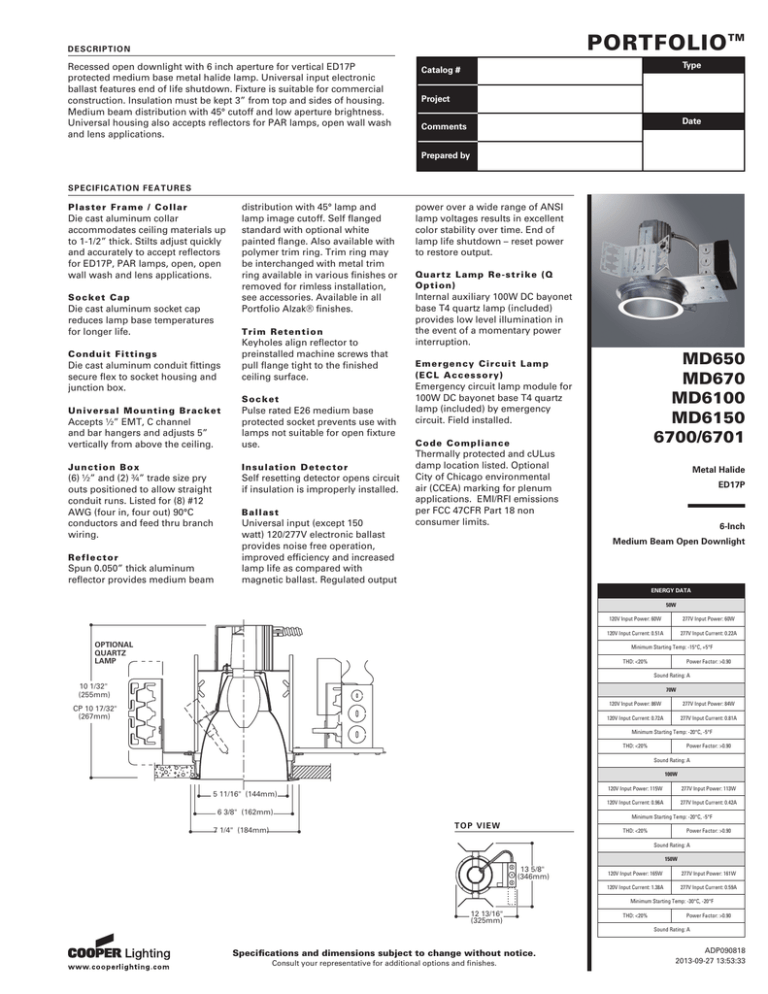
PORTFOLIO TM D ES C R IPTION Recessed open downlight with 6 inch aperture for vertical ED17P protected medium base metal halide lamp. Universal input electronic ballast features end of life shutdown. Fixture is suitable for commercial construction. Insulation must be kept 3” from top and sides of housing. Medium beam distribution with 45° cutoff and low aperture brightness. Universal housing also accepts reflectors for PAR lamps, open wall wash and lens applications. Type Catalog # Project Date Comments Prepared by SPE C IFIC A TION FEA T U R E S Pla s t e r F r a m e / Col l a r Die cast aluminum collar accommodates ceiling materials up to 1-1/2” thick. Stilts adjust quickly and accurately to accept reflectors for ED17P, PAR lamps, open, open wall wash and lens applications. So c k e t C a p Die cast aluminum socket cap reduces lamp base temperatures for longer life. distribution with 45° lamp and lamp image cutoff. Self flanged standard with optional white painted flange. Also available with polymer trim ring. Trim ring may be interchanged with metal trim ring available in various finishes or removed for rimless installation, see accessories. Available in all Portfolio Alzak® finishes. Tri m Re te nti on C on d u i t F i t t i n g s Die cast aluminum conduit fittings secure flex to socket housing and junction box. Keyholes align reflector to preinstalled machine screws that pull flange tight to the finished ceiling surface. Soc ke t Accepts ½” EMT, C channel and bar hangers and adjusts 5” vertically from above the ceiling. Pulse rated E26 medium base protected socket prevents use with lamps not suitable for open fixture use. Ju n c t i o n B o x I ns ul a ti on D e tector (6) ½” and (2) ¾” trade size pry outs positioned to allow straight conduit runs. Listed for (8) #12 AWG (four in, four out) 90°C conductors and feed thru branch wiring. Self resetting detector opens circuit if insulation is improperly installed. U n i v e r s a l M o u n t ing Bra c ke t Re f l e c t o r Spun 0.050” thick aluminum reflector provides medium beam Ba l l a s t Universal input (except 150 watt) 120/277V electronic ballast provides noise free operation, improved efficiency and increased lamp life as compared with magnetic ballast. Regulated output power over a wide range of ANSI lamp voltages results in excellent color stability over time. End of lamp life shutdown – reset power to restore output. Qu artz Lamp R e-strike (Q Op tion ) Internal auxiliary 100W DC bayonet base T4 quartz lamp (included) provides low level illumination in the event of a momentary power interruption. MD650 MD670 MD6100 MD6150 6700/6701 Emergen cy Circuit Lamp (E CL Accessory) Emergency circuit lamp module for 100W DC bayonet base T4 quartz lamp (included) by emergency circuit. Field installed. Co d e Co mplian ce Thermally protected and cULus damp location listed. Optional City of Chicago environmental air (CCEA) marking for plenum applications. EMI/RFI emissions per FCC 47CFR Part 18 non consumer limits. Metal Halide ED17P STEPREPEAT> 6-Inch Medium Beam Open Downlight ENERGY DATA 50W OPTIONAL QUARTZ LAMP 120V Input Power: 60W 277V Input Power: 60W 120V Input Current: 0.51A 277V Input Current: 0.22A Minimum Starting Temp: -15°C, +5°F THD: <20% Power Factor: >0.90 Sound Rating: A 10 1017/32" 1/32" (267mm) (255mm) 70W CP 10 17/32" CP 10 17/32" (267mm) (267mm) 120V Input Power: 86W 277V Input Power: 84W 120V Input Current: 0.72A 277V Input Current: 0.81A Minimum Starting Temp: -20°C, -5°F THD: <20% Power Factor: >0.90 Sound Rating: A 100W 5 11/16" (144mm) 6 3/8" (162mm) 7 1/4" (184mm) 120V Input Power: 115W 277V Input Power: 113W 120V Input Current: 0.96A 277V Input Current: 0.42A Minimum Starting Temp: -20°C, -5°F T OP V IE W THD: <20% Power Factor: >0.90 Sound Rating: A 150W 13 5/8" (346mm) 120V Input Power: 165W 277V Input Power: 161W 120V Input Current: 1.38A 277V Input Current: 0.59A Minimum Starting Temp: -30°C, -20°F 12 13/16" (325mm) THD: <20% Power Factor: >0.90 Sound Rating: A Specifications and dimensions subject to change without notice. Consult your representative for additional options and finishes. ADP090818 2013-09-27 13:53:33 MD650 MD670 MD6100 MD6150 6700/6701 OR D ER ING INFOR M A TION S A M P L E N U M B E R : M D 6 7 0 E = 6” universal housing with UNV 120/277V electronic ballast for a 70W ED17P MH Lamp 6 7 0 1 L I = 6” medium beam reflector, self flanged specular clear low iridescent (Order universal housing and trim separately) Housing Wattage MD6=6” universal MH housing MD6CP=6” universal MH housing, CCEA listed for City of Chicago plenum requirements 50=50W MH lamp 70=70W MH lamp 100=100W MH lamp 150=150W MH lamp Options Ballast Trim Finish E=Electronic, UNV 120/277V 50/60Hz 1 1E=Electronic, 120V 50/60Hz 2 2E=Electronic, 277 50/60Hz 2 6700=6” medium beam reflector, white polymer trim ring 6700X=6” medium beam reflector, white polymer trim ring, standby lamp 6701=6” medium beam reflector, self flanged 6701X=6” medium beam reflector, self flanged, standby lamp Q=Quartz Restrike System Accessible Ceilings Only Alzak Finishes LI=Specular clear, low iridescent H=Semi specular clear ® WMH=Warm haze G=Gold WH=Wheat GP=Graphite GPH=Graphite haze 1 Not available with 150 watt. 2 Available with 150 watt only. B=Black (Omit finish code with baffle option.) Options Accessories WF=White painted flange (self flanged only) BB=Black baffle (polymer trim ring only) WB=White baffle (polymer Trim ring only) HB26=Bar hanger, 26” long, pair HB50=Bar hanger, 50” long, pair RMB22=Bar hanger for wooden joists, 22” long, pair HSA6*=Slope adapter for 6” aperture, specify slope TRM6*=Metal trim ring, specify finish TRR6=Rimless trim ring ECL=Emergency circuit lamp - Accessible Ceilings only H347=347V stepdown transformer, 75VA H347200=347V stepdown transformer, 200VA PH OTOM ETR IC S Candlepower Distribution Curve Spacing Criteria = 0.8 Efficiency = 46.4% Downlight 80° 920 70° 60° 1840 50° 2760 40° 3680 4600 Cone of Light 10° 20° 30° Test No. H28033 MD6100E 6700LI Lamp = 100W ED17P 100W ED17P Distance Fixture to Lighted Plane 5'6" 6'6" 8'0" 10'0" 12'0" 14'0" Initial Footcandles at Nadir 150 108 71 45 32 23 Beam Diameter 4'6" 5'6" 6'6" 8'6" 10'0" 11'6" Coefficients of Utilization Ceiling 80% 70% 50% 50 30 10 50 10 Wall % 70 50 30 10 RCR Zonal cavity method -- floor reflectance = 20% 0 55 55 55 55 54 54 54 52 52 1 53 52 51 50 51 50 49 49 48 2 51 49 47 46 48 47 46 47 45 3 49 46 44 43 46 44 42 45 42 4 47 44 42 40 43 41 40 42 39 5 45 41 39 37 41 39 37 40 37 6 43 39 37 35 39 37 35 38 35 7 41 37 35 33 37 35 33 36 33 8 39 35 33 31 35 32 31 34 3 9 37 33 31 29 33 30 29 32 29 10 35 31 29 27 31 29 27 31 27 Specifications and dimensions subject to change without notice. Customer First Center 1121 Highway 74 South Peachtree City, GA 30269 770.486.4800 FAX 770 468.4801 ADP090818 2013-09-27 13:53:33
